2. Qinsy Database Setup
This page provides an overview of how to create a template database in Qinsy 9.
When a new project is created in Qinsy 9, it is a little different from creating a project in QINSy 8.X.XX:
The main difference is, that the Geodetics are now stored in the project itself, and not in the template anymore
It is no longer possible to modify the Geodetics in the template, the user needs to go to the Geodetic User Interface.
See page: 2. Qinsy Project Setup
On this page:
Relational database
The base for a project is a relational database that will contain all the information about the configuration and the settings like the vessel configuration, I/O parameters etc. This database is called a template and is selected in the Template Manager.
Raw data is logged in a copy of the template database, so both raw data and the configuration and settings used to acquire that data are stored together in one single database (file). For most surveys each database will contain a single survey line.
The advantage of such a single database containing all information belonging to a certain dataset is that settings can be changed on a file-by-file basis without affecting the overall project settings created during the start of the project.
Template Database
To define a template database the user needs to define either a new template database from scratch or use an existing template database as a basis and modify it.
Creating a new empty template database
Start the Setup module from the Console by double clicking on the ![]() icon in the upper half of the window.
icon in the upper half of the window.
The following window will appear:
To create a new, empty template database click on the ![]() button. The program will ask for a database name. Enter a descriptive name for the template, e.g. the name of the vessel.
button. The program will ask for a database name. Enter a descriptive name for the template, e.g. the name of the vessel.
After this the template Setup wizard will automatically start.
Object definition
In the Qinsy Survey software objects are used on which equipment, or measuring systems, are installed. An object can be a survey vessel, ROV, SSS fish, drilling rig or barge.
Qinsy Survey operates in such a way that it is possible to use multiple objects at the same time.
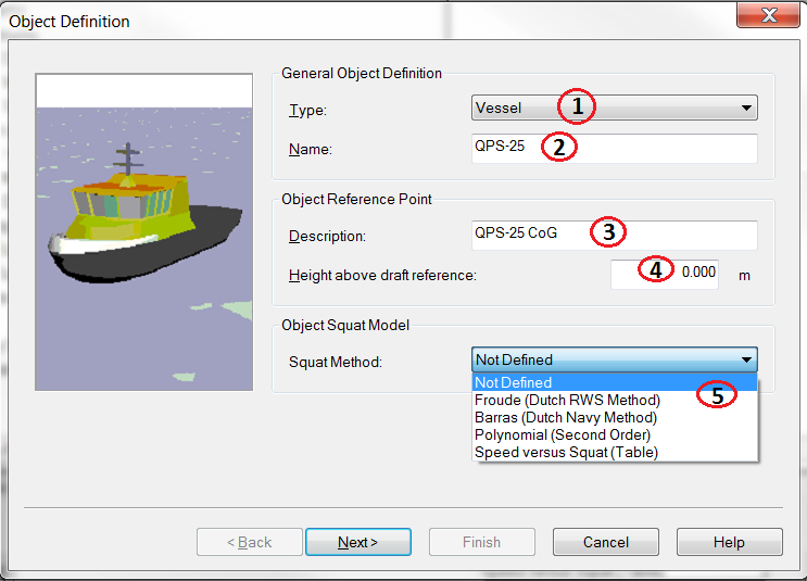
To define the objects needed for the project, the Object Wizard can be used. Clicking on the appropriate icon ![]() with the mouse can start the Object Wizard. The following window will appear:
with the mouse can start the Object Wizard. The following window will appear:
Define an object using the following steps:
Select the type of object; in most cases this will be a vessel.
Enter a name for this object, e.g. the name of the vessel.
Enter a name for the reference point on the vessel. This point will have the coordinates 0,0,0 in the vessel coordinate frame.
It is recommended to choose this point as close as possible to the center of gravity (CoG) of the vessel to ensure optimum performance.Enter the distance between the object reference point and the draft reference of the vessel. The draft reference is the point on the vessel where the draught is zero.
This would normally be the keel. If the object reference point is above the draft reference level, then this value is positive. If the object reference point is below the draft reference level, then this value is negative.Select the type of squat model to be used.
Information
See the 'Height' documents in the Knowledge Base for more information about the 'height above draft reference'.
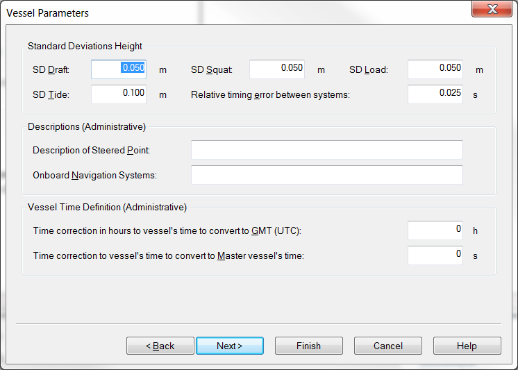
Vessel Parameters
Enter a-priori standard deviations for draft, squat, load, tide and relative timing errors between systems.
Information
These SD’s are only used in case a position system height is set to Unreliable in the Computation Setup; otherwise the SD of the position system height observation is used. See Height Aiding Driver Window.
Information
The Vessel Parameters page is only available when object type is Vessel or Survey vessel. The other fields on this page only serve administrative purposes and are not applicable to the computation of TPE values.
See for more information the document 'How-to Total Propagated Uncertainty - TPU' in the Knowledge Base.
Shape definition
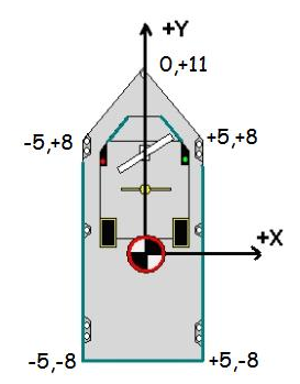
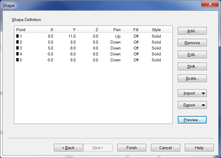
The next screen in the Object Wizard depends on whether the squat box was checked or not. Since the squat parameters are unknown for most vessels, this will not be discussed further. Next the shape definition screen will show. The object shape is used online in the Navigation Display to give the user an idea of the shape of the vessel and the heading. It is possible to define the shape manually or to import a vessel shape from a previous project. See the picture below for the sign conventions on the X and Y axis and for an example of the X and Y of the points of the vessel shape.
Select Add and enter the points of your vessel shape one by one
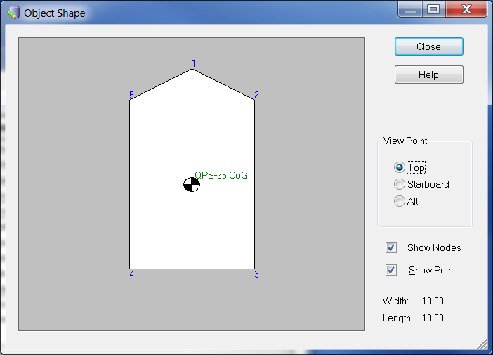
Click on Preview to see the result
Information
The object shape is defined as a series of X, Y points. Depending on whether the pen is UP or DOWN during drawing a line is drawn connecting two subsequent points or the pen is moved.
It is also possible to fill a polygon with a certain color or to use a different line type.
System definition
Having defined the geodetic parameters and the object, the next step is to define the systems that are going to be used during the survey.
Systems include measurement devices like GPS, echosounder and gyro compass. To define a new system, click on the icon ![]() .
.
System selection
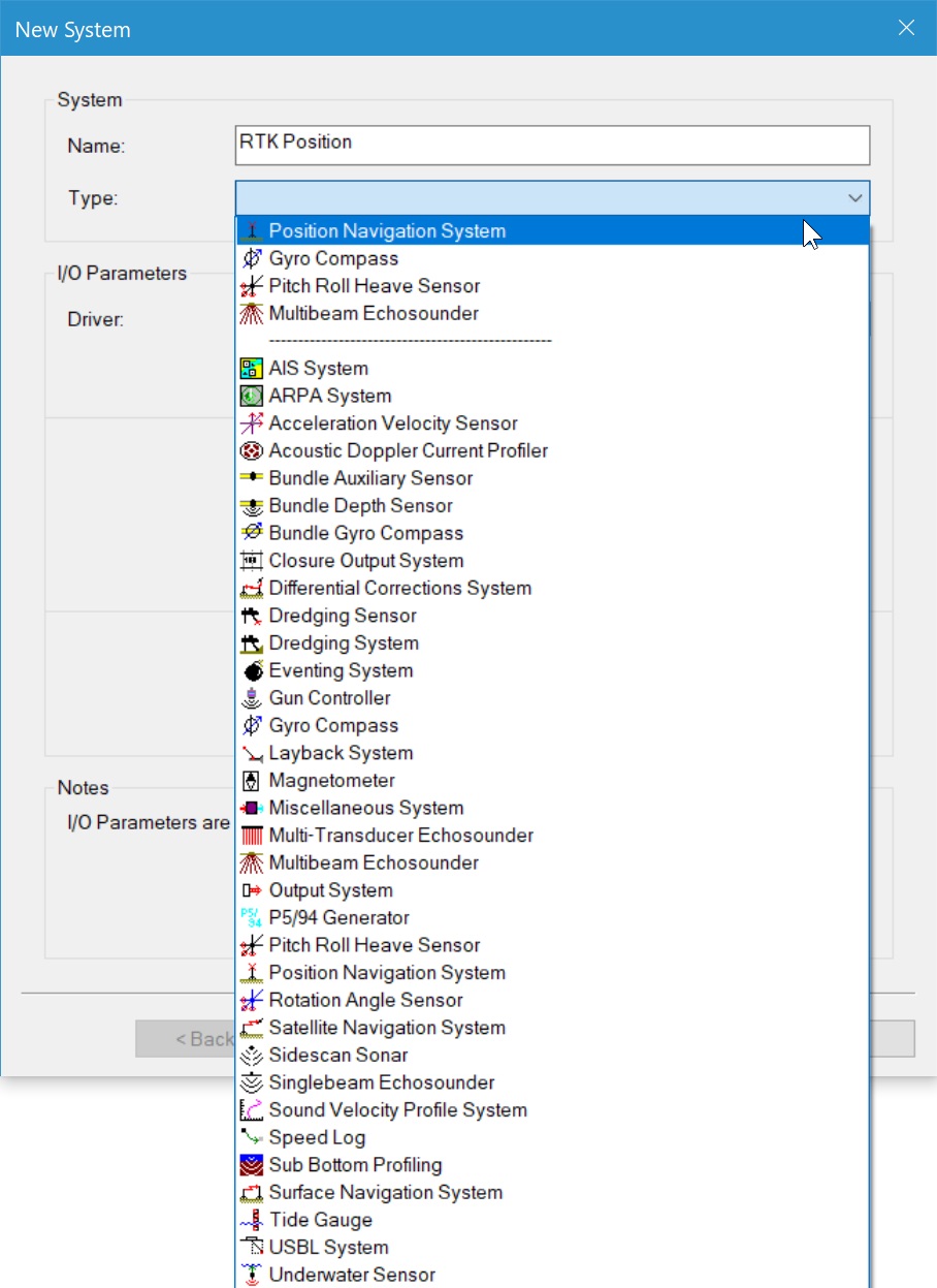
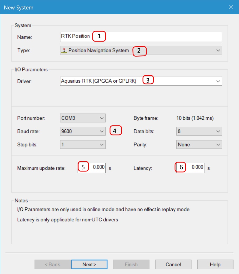
To enter a new system the following steps need to be taken:
Enter a descriptive name for the system.
Select the type of system. A complete list of system descriptions can be found in the online help.
Select the corresponding driver (software program that decodes the data string) for the system to be installed.
The different output formats are specified in the QINSy Drivers and Interface Manual that can be found in the QINSy Console or on the QPS website.Enter the correct values for the interfacing of the sensor with the computer, the correct COM-port with the correct parameters.
More information about this can be found in the manual of the system or on the system itself.If the system outputs at a higher frequency than is needed for the survey (e.g. for a gyro compass), a maximum update rate can be entered.
This means that data from the system is decoded only every x seconds. A value of 0 means that all data will be decoded, 0.2 means 5 samples per second.If the data that is output to the computer has latency, then a constant latency for that system can be entered here.
Information
Latency for the GPS system should preferably be measured using a Time Synchronization System (formerly PPS) output from the GPS receiver. If a PPS output is used then the latency of the GPS receiver should be entered as zero in this field.
The value entered in this field is used during an Online session. Changing it has no effect during Replay.
Information
If a data string from an instrument is in ASCII format and no driver is available for the instrument then it is possible to generate a new driver.
Use the I/O Driver Editor from the Qinsy Console.
Note
Always read the Drivers and Interface manual before interfacing a system to Qinsy.
System parameters: system location
The next window shows the parameter settings for the selected system. The layout of this screen depends on the selected system type.
All systems require as a minimum the object's name on which the system is located and the location of the system on that object (with the exception of heading systems).
The location of a system on an object is called a Variable Node.

Create a node for each antenna or transducer. Clicking on the ![]() button creates a new node, or edit an existing node using the
button creates a new node, or edit an existing node using the ![]() button.
button.
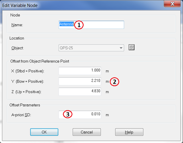
Enter a name for this new node.
Enter the offsets for this node relative to the reference point (0,0,0) of the object.
Enter the a-priori SD of this offset measurement.
Information
Every time a new node is created, it is stored as a new Variable Node in the list.
System parameters: GPS receiver
Apart from setting the location of the system with respect to the reference point of the object, a number of other parameters need to be set:
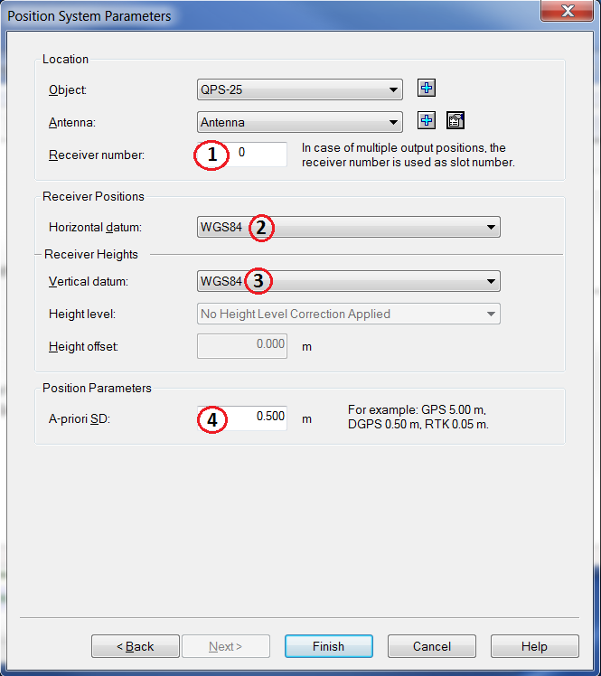
If more than one receiver is used on the vessel, enter a different receiver number for each one.
Define the datum on which the receiver measures its positions. Normally this will be WGS84 for horizontal datum.
Select the datum on which the heights are measured. For most GPS receivers this is either WGS84 or the Mean Sea Level (Earth) model.
Define the a-priori SD from the positioning system.
System parameters: Echosounder
On the first page of the echosounder setup the name, system type, driver and interface settings are defined.
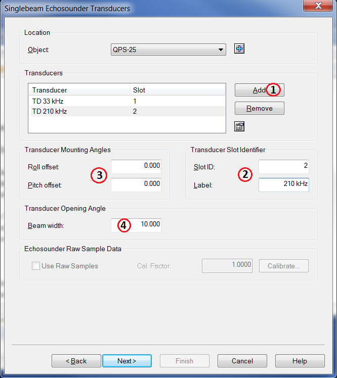
Add each transducer to the transducer list using the add button and then selecting the node.
Select the transducer in the list and set the slot number and the label.
Set the mounting angles of the transducer.
Enter the beam width.
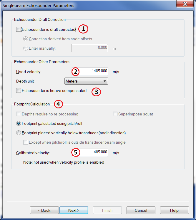
Enable this option when the draft is entered in the echosounder itself.
Input the velocity that's entered in the echosounder itself.
Enable this box if the motion sensor is connected directly to the echosounder and the output soundings are already corrected for heave.
Select how the footprints should be calculated.
Enter the true sound velocity.
Information
See for a more detailed description of these parameters the F1 inline help or the document 'How-to Singlebeam Settings' in the Knowledge Base.
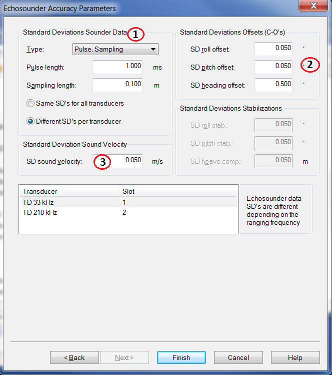
Enter the Standard deviations for the echosounder; for each transducer a different SD can be defined.
Enter the a-priori SD for the roll-, pitch- and heading offsets.
Enter the SD of the sound velocity.
System parameters: Multibeam Echosounder
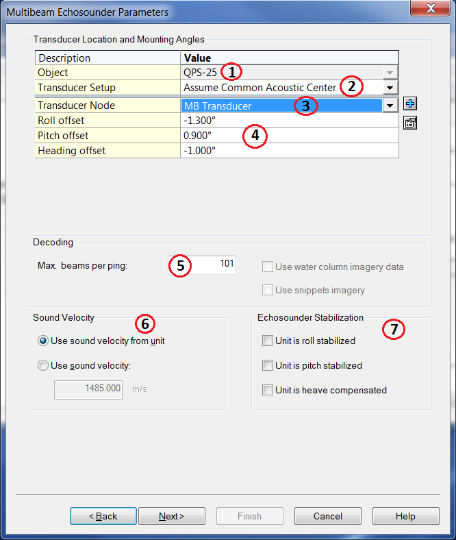
Select the object on which the multibeam is located.
Select the type of transducer setup. This could either be an assumed common acoustic centre or Separate transmit (TX) and receive element (RX). The latter is common for deep water systems.
Select the transducer node or create a new variable node.
The transducer mounting angles are determined during the Multibeam calibration, see for more information the document 'How-to Calibrate Multibeam' in the Knowledge Base.
Enter the number of beams per ping (sweep). The number of beams depends on the system used.
Select the source of the sound velocity. If the unit has its own sound velocity probe mounted near the transducer head or if the sound velocity is in the output message, then the sound velocity from the unit should be selected.
Otherwise enter the sound velocity here. When online it is possible to create and select a Sound velocity profile to correct for refraction.Check the appropriate boxes if the unit (and the output message) is stabilized for roll, pitch or heave.
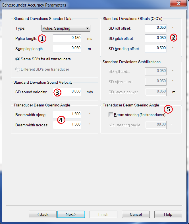
Enter the standard deviations for the multibeam system.
Enter the a-priori SD for the roll-, pitch- and heading offsets.
Enter the standard deviation of the sound velocity.
Enter the Transducer beam opening angles.
Enable this option if a flat transducer is mounted.
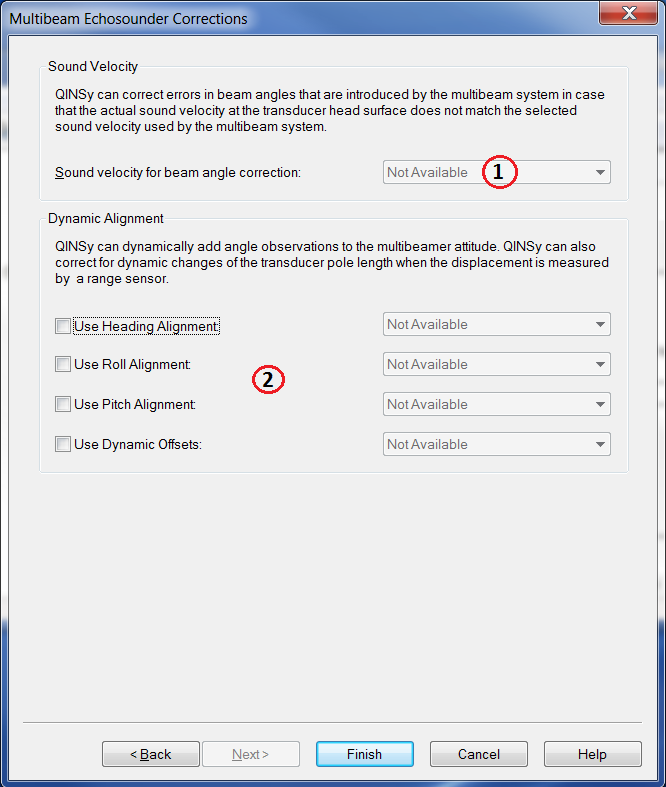
If a sound velocity probe is installed close to the transducer of the multibeam system and is interfaced into Qinsy, then you can optionally select it here.
If an angular system is available for MBE alignment corrections, enter the system here.
System parameters: Gyro compass
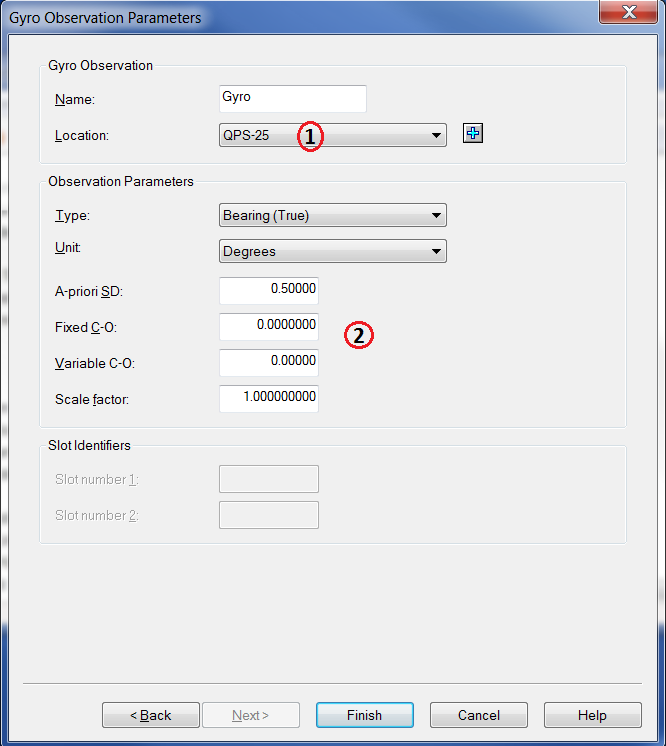
Select the object on which the gyro compass is located.
For a normal gyro compass installation all values as shown here are already correct. The only value that will change during the start-up phase of the project is the fixed system C-O.
This C-O is determined during the gyro calibration.
System parameters: Pitch, roll and heave sensor
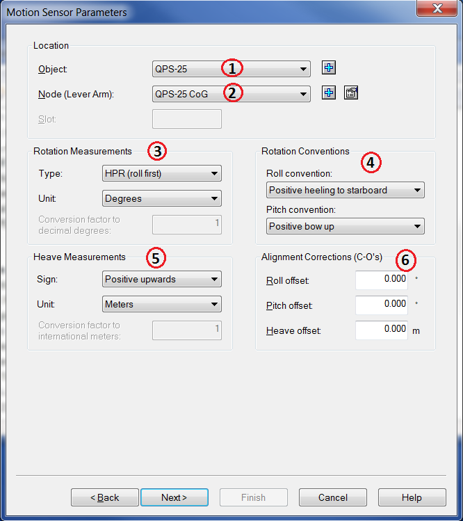
Select the object on which the motion sensor is located.
Select the node on the object where the sensor is located. If the offsets to the reference point are entered in the motion sensor itself, select the reference point.
Enter the rotation measurements. These settings for Rotation Measurements "Type" depend on the motion sensor.
Under “Rotation Measurements” enter the angle parameters for pitch and roll. These can be found in the manual of the system or in the Drivers and Interface Manual.
Enter the sign and unit for the heave measurement.
Enter the C-O offsets of the MRU sensor.
Note
It is very important to mount the attitude sensor (pitch, roll and heave) in the correct location. QPS advises the use of a location as close as possible to the Centre of Gravity (CoG).
If the sensor is installed away from the CoG then the offset between the CoG and the sensor should be input in either the software or the sensor.
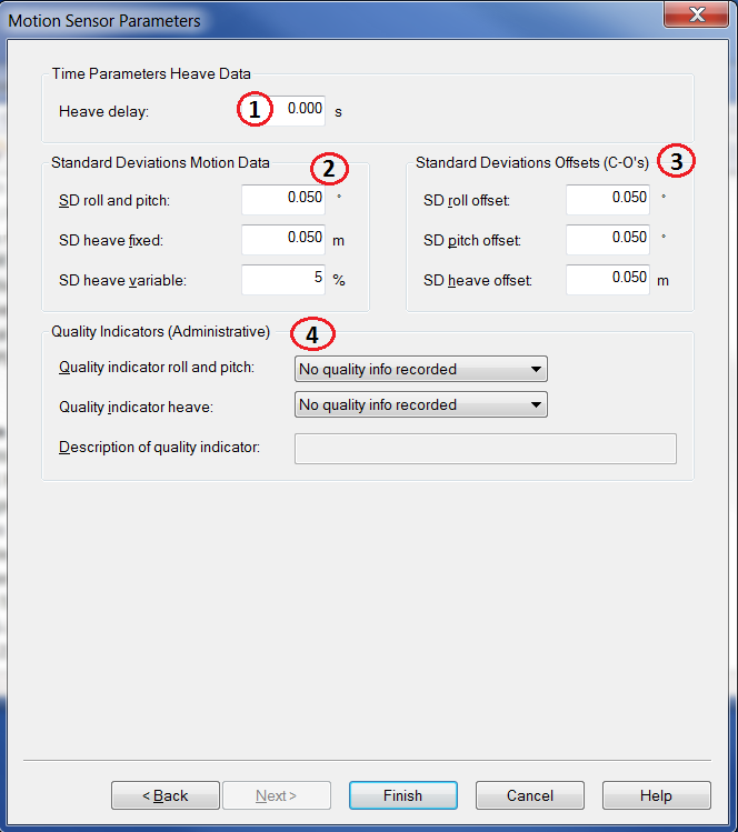
Enter the delay for the calculated heave inside the motion sensor algorithm.
Enter standard deviations for the motion data.
Enter standard deviations for the offsets.
Enter quality indicators, these fields have no effect on the data.
System parameters: PPS
A PPS system is used to synchronise the Qinsy system to UTC time. To do that a TTL time pulse and GPS time are used. The GPS receivers send out a pulse and a time string every second.
The TTL pulse is converted into a serial string with a PPS-TTL converter which is connected to COM1 or 2 (this depends on which driver you have selected, baud rate etc. are predefined).
For the GPS time string a driver has to be selected and this string arrives at another COM port.
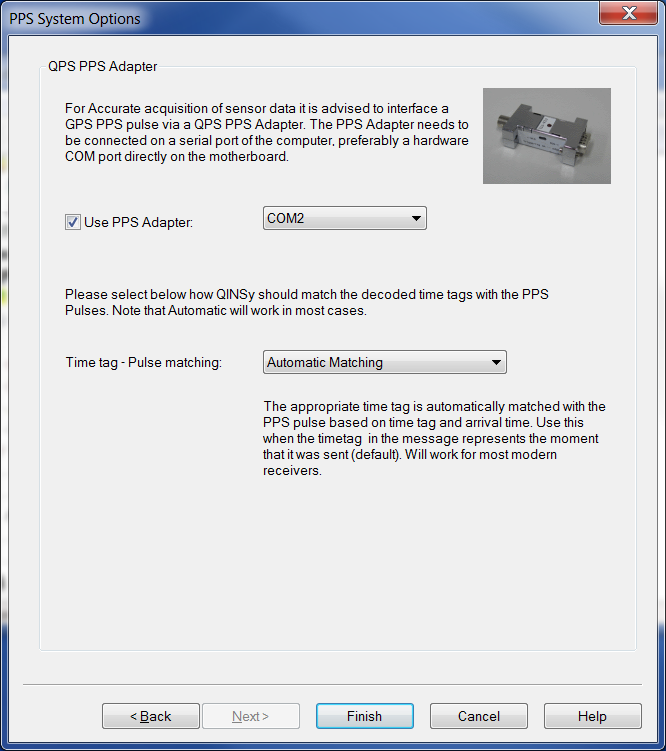
The explanation of the above settings can be found in the PPS System options Help page.
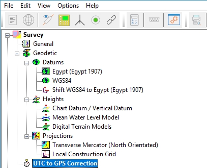
GPS time and UTC time are not the same, there is at the moment a difference of 18 seconds (2017). The time correction must be defined in the survey part of the Database Setup.
This time correction will only be used in Qinsy if a system outputs the data in GPS time, then this correction will be added.
Read more
See the 'How-to Tow Fish or ROV' to add a secondary object to the template database.
Read the 'How-to Apply Tide' to add tide gauges to the template database.
Use the 'How-to Sidescan Sonar' to add a sidescan sonar system to the template database.
Return to: 2. Qinsy Project Setup


