How-to Cable/Pipe Detection and Editing
This How-to document describes how to detect and edit a cable or a pipe line from multibeam data.
There are also ways of detecting a pipe from a cable/pipe tracker system, for which we will add the information later on.
Part 1 of this article explains the cable/pipe detection. Part 2 explains the cable/pipe editing and smoothing.
Introduction
To use the TOP (Top of Product) tools, a Qimera Offshore License is required. The Qimera Offshore license will work with Qimera 2.4 and newer. Before getting started and using the tool, ensure you have the following information available in the Qimera project:
Dynamic Surface built from the survey data, preferably built at a small bin size.
Add shading to the surface for more context and you may want to do a visual inspection on where the cable/pipe is sitting.
For the best results, you may want to be using a data set that is free of noise and spikes around the cable/pipe.A qgf line file or a CAD file of the design cable/pipe or the as-laid cable/pipe. The file should contain KP values. This file can be created in Qinsy Survey Manager if needed or by using the Profile and/or Measure tool in Qimera to draw a line along the cable/pipe and when finished, right click and select "Create Route from Current Selection". When the line is loaded into Qimera you will need to promote it to a Project Route by right clicking on the SD line object and selecting "Use Line Object as Route".
For the cable/pipe detection, it helps if you know the cable/pipe diameter. When in doubt, you can use the measure tool in Qimera Slice Editor.
Part 1 - Cable/Pipe Detection
There are basically two ways of cable/pipe detection:
Automatically - which processes the entire line or within a custom range.
Manually - by doing single detections.
Both methods will be discussed in this article.
The first method, the automated cable/pipe detection on the entire line, works really well, if the survey data is of good quality. When the surface is free of spikes and noise, the automated cable/pipe detection will do the job.
The manual processing, method 2, can be done on the entire line, but it's time consuming. When the automated cable/pipe detection went well, you would only need to adjust the detected cable/pipe manually on some portions of the data.
Method 1 - Automated Cable/Pipe Detection - Entire Line Processing
In the Project Layers dock, right click on Route, then choose to Load a Route from the QGF File.
This step is needed in order to make the route available in the Qimera project.
Another way of doing this, is to select the Sd file of the cable/pipe, which was brought in as CAD, right click, use Line object as route.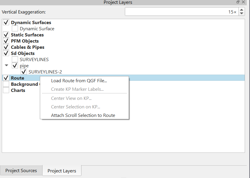
Ensure to have a Dynamic Surface available from where the cable/pipe needs to be detected from.
The Cable/Pipe Detection tool won't run on a static surface.
A dynamic surface can be built in different ways: it can be the surface built from processed data in the Qimera project. It may also well be built from an XYZ ASCII file that was brought in as processed points.
Look here for more info.From the Tools dropdown menu, select Cable/ TOP detection tool.
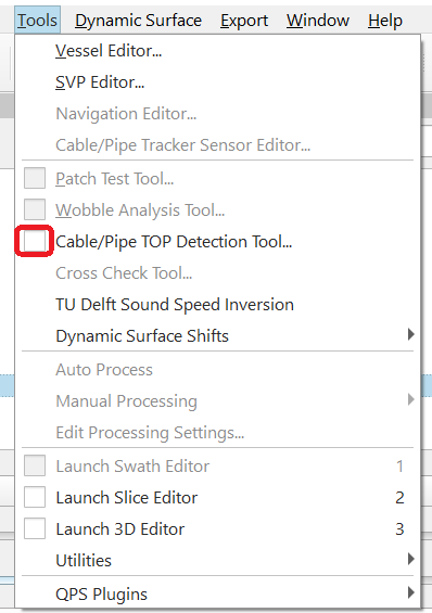
This launches the GUI for Cable/Pipe TOP Detection tool.
Ensure to set the correct settings.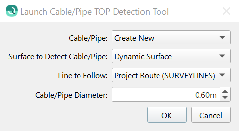
OK this.Two hot dockable windows have now opened:
1) the TOP Detection Control Window and
2) The Top Detection Results Window.
Also, on 4d main view, you will see the polyline used as scroll reference and a selection box drawn perpendicular to that scroll line.
A cross section of the data selected inside the scroll box is shown in TOP Detection Control Window.
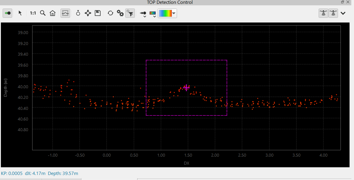
This is what needs to be looked at first.In the TOP Detection Control dock, in the cross section view, on the toolbar click on Select Tracking rectangle

and draw a rectangle over the soundings that make up the cable/pipe:
Click on the Settings button (double gears)

.
This opens the Tracking Options dialog: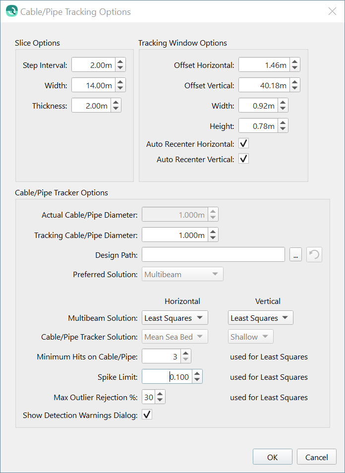
The Cable/Pipe Tracking options are explained Qimera TOP Detection Settings Dialog .On the TOP Detection Control toolbar, click on Do Single Detection button

.
This is to check the first single detection, which is the current solution, in order to see if this detection goes well and to check if you have made the correct detection settings.
The first time you click on this button, the options dialog (mentioned in step 5) will open.OK this and you should see the first detection made within the selection. The detection is shown as the circle:
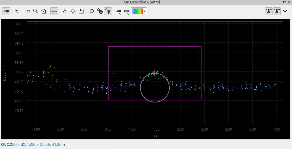
If this looks promising, then proceed with next step.
If the cable/pipe is in the wrong place, then check the settings by clicking on the double gears button
.
Click on Processing button

.
This opens the Detection Range dialog. Choose to detect the cable/pipe of the entire poly line or a custom range.
You may first want to try the detection settings on a custom range, by setting the min and max KP value, just to see how it goes.
When you are happy with the results, you can run the automated detection on the entire line.
When it's a long cable or pipe line, the custom range pipe detection may be the preferred way of doing this.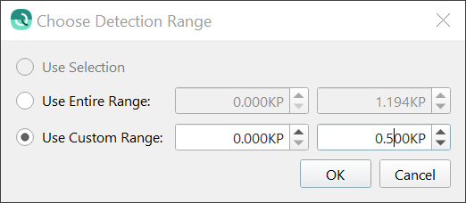
Click on OK to kick the detection tool.
You should see a message box showing the detection progress: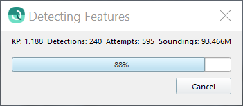
You may want to check the number of attempts against the number of detections.
When there are few detections and many attempts, you may want to cancel the process and double check the detection settings.
When the detection has finished, there may be warnings, these may be saved to a file.
OK the warnings dialog.Ensure the cable/pipe is enabled under Cables & Pipes in Project Layers dock.
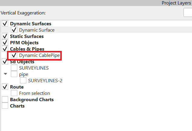
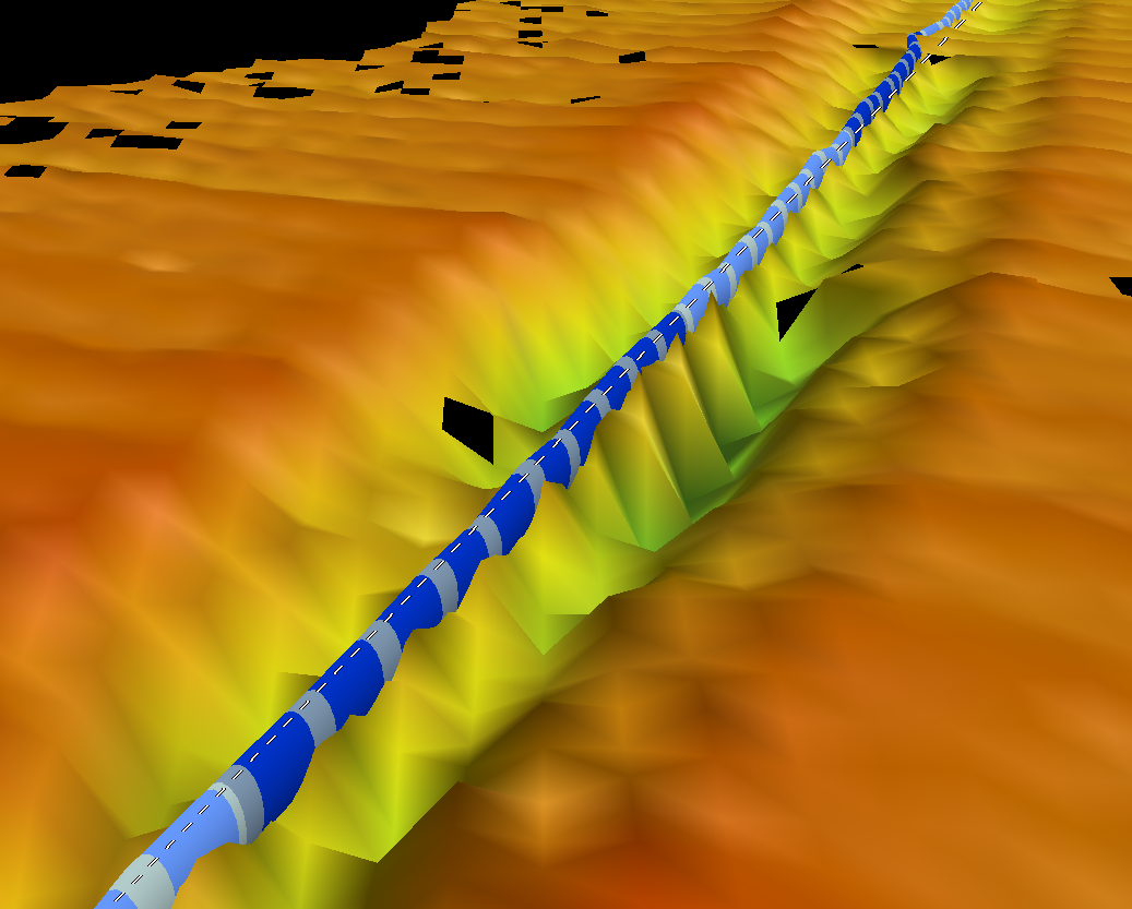
This way, you will find the detected cable/pipe shown on the 4D main display:
You can navigate/rotate on the surface by holding the shift key down and using the left mouse button to rotate, using the mouse scroll wheel to zoom in/out and using the middle mouse button click to re-center the view.The detected cable/pipe is shown in the TOP Detection Results window.
QC the detected cable/pipe results.
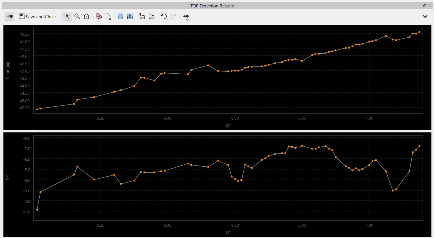
You can edit and smooth the detected cable/pipe in TOP Detection Results Dock.
How to smooth and edit a detected cable/pipe see Part 2 - Cable/Pipe Editing further down this page.Use Cable/Pipe analysis tool to analyze the cable/pipe and to export the x-points listing.
Info
The automated detection tool may take some time to finish.
This is because the algorithm needs to make decisions and this just takes time.
It is quicker than the manual detection.
Method 2 - Manual Cable/Pipe Detection - Single Detection
This method can be used in addition to the automated cable/pipe detection (Method 1).
This method can also be used to manually detect the entire cable or pipe line, in case the survey data is of poor quality and the automated detection has trouble finding the cable/pipe in the DTM.
The first steps are similar to the steps of Method 1 - automated processing, Step 1 - 8.
At step 8, when you find the cable/pipe is at the wrong location, you can manually move the cable/pipe to the correct location.
Use the button Move Cable/Pipe Manually
.
This allows for moving the portion of the cable/pipe selected within the slice to the desired location.
Just hold the left mouse key on the circle and move the circle to the desired location.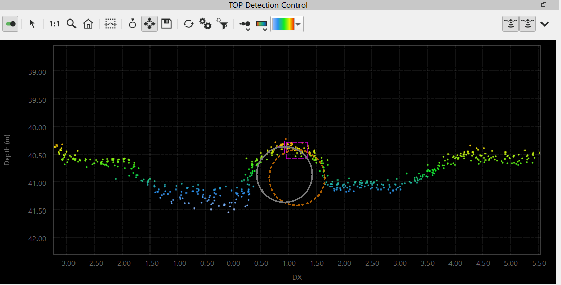
Then save.You can move the selection forward by using the W key on the keyboard.
To move the selection backwards, use the S key.
Do another single detection by using the Do Single Detection button
.
If you are happy with the detection, then save.
If you need to adjust the detection, manually adjust as explained in step 2 et cetera.Repeat the single detections until you have finished the entire line.
From here continue at step 12 of Method 1 - Automated Cable/Pipe Detection
Info
You can apply an automated data cleaning filter to the soundings in order to reject spikes during cable/pipe detection.
This can be achieved by clicking on the "Run Filter profile during detection" button on the TOP Detection Control Window tool:
The filter to apply can be setup in the filter toolbar, look here for more information.
Info
Use the Cable/Pipe Tracking Options to change the slice dimensions if needed: 
This is sometimes needed, when the single detection can't be done.
This may happen when the selection is too far away from the surface.
Drawing a new rectangle may also help.
Part 2 - Reviewing and Editing the Detected Cable/Pipe
Reviewing and Editing the Detected Cable/Pipe
Once the cable/pipe has been detected, the detections are displayed in TOP Detection Results dock.
The vertical red dotted line in the TOP Detection Results dock shows where the selection is at:

In this example, there is a spike in the detections, which also displays in TOP Detection Control dock as a wrong solution.
This can be solved in different ways: 1-2-3
In Top Detection Results dock, Ctrl+ click to the spike and delete the spike using the "delete detections" button on TOP Detection Control Toolbar

This will delete the spike and the detections will be interpolated. Click Save and you will notice the cable/pipe has updated.In TOP Detection Control it can be solved by redrawing the tracking rectangle constrained over a smaller area and do a single detection. Check if it is a good solution, then Save and you will notice the cable/pipe has updated.
In TOP Detection Control you have the option to use the Move key

(see Manual Cable/Pipe Detection on this page) and drag it to where you think there is a good solution.
When you are happy, click Save and you will notice the cable/pipe has updated.
Cable/Pipe Smoothing
Cable/Pipe smoothing options are available in Top Detection Results dock.
Select the sample range you want to smooth by clicking on the Sample Range Selection button![]()
To undo the selection, use the Explore button![]()
A smoothing option can be chosen by clicking on the Edit Smoothing Settings button![]() .
.
There are two methods available for smoothing: Boxcar Averaging and LOWESS
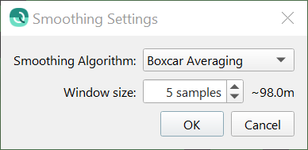
Look here for more information on the smoothing settings.
To smooth all detections, use the Smooth All
To undo, use the Undo button
Save when you are happy and the cable/pipe detections will update.
Do a visual inspection on the 4D main display.
To get to product deliverables, use Cable/Pipe analysis tool to analyze the cable/pipe and to export the x-points listing.
