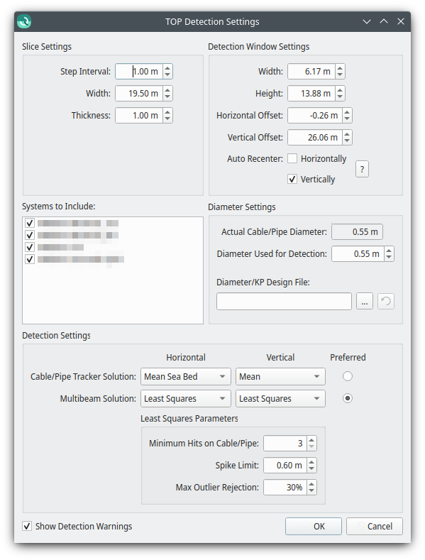
Qimera TOP Detection Settings Dialog

The TOP Detection Settings dialog is used to configure the parameters of the TOP detection algorithm, and is split in to three main sections:
- Slice Settings
- When processing the entire line, Step Interval represents the along track distance between detection attempts
- Width and Thickness represent the size of the Scroll Selection window in the across track and along track directions, respectively.
- Detection Window Settings
- Width and Height represent the size of the tracking window in across-track and depth directions, respectively.
- Horizontal Offset and Vertical Offset represent the centre of the tracking window to in across-track and depth directions, respectively.
- The Auto Recenter settings control automatic recentering of the detection window. If checked, the detection window will automatically be recentered on the last successful detection before attempting the next detection.
- Vertical recentering is very useful when dealing with varying elevation.
- Horizontal recentering can be useful when the across-track position of the cable/pipe varies significantly.
- However, automatic recentering can lead to detections "drifting off", especially in areas without a pronounced cable/pipe.
- Systems to Include
- This checkable list of systems controls which systems will contribute soundings to the detection process. Unchecking all systems of a particular type will disable some settings specific to that type of sounding. At least one system must be checked.
- This system selection is mirrored in toolbar of the TOP Detection Control dock.
- Diameter Settings
- These settings apply only when detecting a pipe from multibeam points.
- The Actual Cable/Pipe Diameter field shows the the nominal diameter of the cable/pipe,
- The Diameter Used for Detection is the diameter used by the detection algorithm will used to determine the cable/pipe's location. Normally this should be the same as the actual diameter, but can be changed to accommodate special scenarios:
- The detection diameter can be set larger than the actual diameter to handle sections where the cable/pipe is wrapped in a protective collar.
- The detection diameter can be set smaller than the actual diameter to handle "piggyback" setups where a smaller cable/pipe is placed directly on top of a larger one.
- Alternatively, loading a Diameter/KP Design File file allows the user to specify a varying detection diameters as a function of the project KP.
- Detection Settings
The Multibeam Solution and Cable/Pipe Tracker Solution options refer to the particular method used to determine the horizontal and vertical positions of a detection. The following options are available:
Detection methods Fixed Value Used to detect at the middle of the tracking rectangle. Shallowest Used to detect using the shallowest data point, within the tracking rectangle. Deepest Used to detect using the deepest data point, within the tracking rectangle. Mean Sea Bed Used to detect using the mean value of all samples within the tracking rectangle. Least Squares Used to detect using the least squares method on all samples within the tracking rectangle. - When using the Least Squares algorithm, there are additional options available
- The detection attempt will not succeed if the tracking window contains fewer points than specified by the Minimum Hits on Cable/Pipe.
- Spike Limit determines how large a spike can be and still be included in the LSQ calculation.
- Max Outlier Rejection is the percentage of points in the estimation window that can be determined to be outliers before the detection attempt fails.
- When doing detection with both multibeam and cable/pipe tracker systems, the Preferred radio buttons are used specify which detection type should be preferred in the case that both types of detection succeed.
- If checked, the Show Detection Warnings option will show a dialog listing any warnings generated by the detection algorithm after each detection run.
