
How-to Spline Filtering details
This documents explains the QPS Spline Filter. It also provides an example of how to apply the Spline filter in Qimera.
On this page:
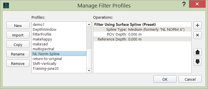
In Qimera 1.3 the predefined spline filters were renamed:
| Qloud filter name | Qimera filter name |
|---|---|
| Extremely High Detail | Very weak |
| NL Norm A | Weak (NL Norm A) |
| SMA Exclusive Order | Weak |
| NL Norm B | Weak (NL Norm B) |
| IHO Special Order | Medium |
| IHO First Order | Strong |
| IHO Second Order | Very strong |
Introduction to Spline
The QPS Surface Spline Filter was developed in 2002 for use in Qloud.
The underlying principle of this filter is that it attempts to fit a surface through noisy multibeam echosounder data and clip all footprints that lie too far from this surface.
The QPS Surface Spline Filter does more or less the same as a data processor would do manually, i.e. it attempts to determine what the bottom, or a feature on the bottom, is by fitting a surface spline through the noisy footprint data and filter out any footprints that lie far away from this surface.
The filtering is done in two passes:
- The first pass will create a spline and identify large blunders.
- A second pass will create a refined spline used to flag soundings.
The surface spline used in this algorithm is known in literature as a Thin Plate Spline. Please see Additional Information at the end of this How-to for articles by Bookstein and Belongie on the thin plate spline and its application.
The First Pass
A surface spline will be deformed if large spikes are present. In other words, blunders (large spikes in the data) have an effect on the fitted surface. These spikes need to be removed to achieve a surface that fits ‘nicely’.
A surface spline is considered a nice fit, if the Root Mean Square of all differences between the surface and the actual points is smaller than the set threshold. This value will be called the deviation.
The threshold is the first filter parameter and is expressed as a percentage (default 0.5%) of the depth.
As the surface is calculated if the deviation is larger than the threshold, four points are removed from the spline dataset:
- the footprint with the maximum height
- the footprint with the minimum height
- the footprint with the largest positive difference with the surface
- the footprint with the largest negative difference with the surface
The surface is then recalculated and if the deviation is now below the threshold, the surface is determined to be a ‘nice’ fit. If the deviation is still above the threshold, four points are removed again, as described above and a surface is fitted again. This process iterates until either the deviation target is reached, or more than half of the initial points are discarded.
As soon as a surface that fits nicely is available, all points that have a larger difference are filtered out. The parameter is the first-pass SD factor.
The Second Pass
Once the largest errors are filtered, all remaining points are used to create a new spline surface. This second pass is then used to filter out all the soundings that lie farther than the calculated distance from the new spline surface. The parameter used here is the second-pass SD factor.
Note that points that were filtered in the first pass can be unfiltered in this pass. This is needed since the surface that was determined in the first pass was calculated with a reduced data set.
How to select and apply the spline filter
The Spline filter can be applied via the Filter Profile Operation Toolbar or the Slice Editor. Please see these pages for more information:
How-to Filter Operations and Filtering Profiles
Spline Technical Information
Approximations for the IHO specifications below have been pre-configured and are available as preset spline filters in Qimera.
| IHO S44 | Depth Range(m) | a | b |
|---|---|---|---|
| Very Weak (Extremely High Detail) | 0 - 10 | 0.05 | 0.00020 |
| Weak (Exclusive Order) | 0 - 20 | 0.15 | 0.0040 |
| Medium (Special Order) | 0 - 20 | 0.25 | 0.0075 |
| Strong (First Order) | 20 - 50 | 0.50 | 0.0130 |
| Very Strong (Second Order) | 50 - 100 | 1.00 | 0.0230 |
NLNORMA and NLNORMB - The NL Norm A and NL Norm B filters have been determined by the Dutch Government to comply with RTK fixed surveys in shallow waters. These filter presets are only available when creating a new filter profile.
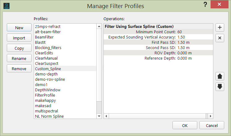
Creation of Custom Spline Filter
The Filter Operation Toolbar allows for the creation and application of custom filters.
Here is a brief summary of the Spline Filter parameters:
- Number of points - The number of points processed at once. If this number is reduced, the filter takes significantly less computation time, but accuracy is affected. Intuitively, one can understand that if not enough points are considered, a local cluster of blunders may be considered as a valid surface. The number of points should be set as high as possible, while a reasonable filter speed is maintained. A higher number of data points will allow the filter to more accurately follow the surveyed terrain.
- Sensor Level:
- Reference Level:
- The first-pass Standard Deviation factor. Recommended range: [1.0 … 4.0], where 1.0 is a strong filter action and 4.0 a weak one. It is important that this factor is set to such a value that large blunders are eliminated, so it should not be too high. Since the surface spline determined in the first pass is not as accurate as the spline of the second pass, this factor should also not be set too low, to prevent the accidental filtering of valid data points. A good starting point seems to be: 2.0.
- The second-pass Standard Deviation factor. Recommended range: [1.0 … 4.0]. This is the most important parameter in my opinion. Once a surface with a certain difference to the original data points has been determined, this parameter determines if a point is filtered or not.
- Approximation factor, expressed in a percentage of the depth. This is similar to the IHO orders that specify a minimal vertical Total Propagated Uncertainty to be achieved when surveying. One can say that the expected accuracy of the survey must be used as this parameter.
It's the QPD's that are filtered by the Spline Filter. DS-es built from Spline Filtered QPD's will update accordingly. This might implicate a re-build for multiple DS-as after spline filter application and this might clarify cases of all DS-es being rebuilt after Spline filer application.
For a start, run the Spline Filter on a small area for testing with the Slice Editor. When you're happy with the results, run the filter on the entire survey. Please note this suggestion only applies to an area with little seafloor variation.
To un-reject soundings rejected by the Spline filter, use the Revert All Filtering function, which is available from the Filter Operation Toolbar
Additional Information
Papers on thin-plate spline filters and their applications:
"Principal warps: Thin-plate splines and the decomposition of deformations" - Bookstein, F.L.- IEEE Transactions on pattern analysis and machine …IEEE Transactions on Pattern Analysis and Machine Intelligence, 11(6), 567-585., 1989. Retrieved from http://user.engineering.uiowa.edu/~aip/papers/bookstein-89.pdf.
"Approximate thin plate spline mappings" - Donato,G., Belongie, S. - Computer Vision—ECCV 2002, 2002 - Springer. Retrieved from http://vision.ucsd.edu/sites/default/files/fulltext(4).pdf.
"Shape matching and object recognition using shape contexts" - Belongie, S., Malik, J., Puzicha, J. - Pattern Analysis and Machine …, 2002. Retrieved from http://staff.science.uva.nl/~rein/UvAwiki/uploads/HVisser/Shape_Matching_and_Object_Recognition_Using_Shape_Contexts_Belongie_Malik_Puzicha.pdf