FMGT - Settings Menu
The settings menu provides control over the processing options for FMGT.
It also allows you to edit the current project coordinate system or set up a directory for active monitoring.

Settings Menu
Processing Parameters
The Processing Parameters dialog provides options for the processing stages of FMGT.
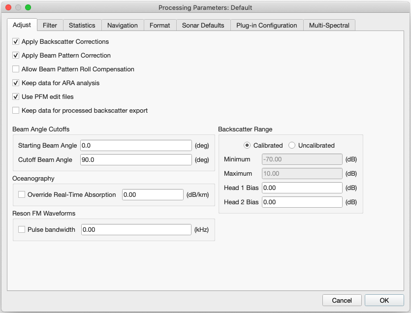
Processing Dialog – Backscatter Options
If you modify any of the processing parameters, you must re-process your data. See the Processing Panel section to see how to accomplish this.
Backscatter Options
The Processing Dialog – Backscatter Options figure shows the options available for the backscatter stage of processing.
The Apply Backscatter Corrections option will turn on/off all backscatter related corrections for the data. This option is on by default and will apply all of the radiometric correction algorithms appropriate for the particular sonar. Being able to disable the backscatter corrections is particularly helpful when troubleshooting problematic data. You can disable this option to see if any problems that you notice in your mosaics are embedded in the data itself, or if they are being introduced by the backscatter processing that is done in FMGT. That being said, our recommendation is to leave the backscatter corrections application enabled as per the default.
If users decide to disable this option, FMGT will not perform any of the usual backscatter corrections at all. This will give the ability to create mosaics of raw sensor imagery. Note that the raw sensor imagery will be influenced by all of the changes in sensor configuration during acquisition and the data range may deviate significantly from the expected range for backscatter. For non-Kongsberg users, you will also need to adjust the Backscatter Range options to be Uncalibrated and also adjust the signal range to match the raw sensor imagery. For Reson, R2Sonic and Norbit users, this raw range would typically be a Minimum of 0 and a Maximum of 97. This is done in the Backscatter Range section of the same tab, see description below. For Kongsberg systems, the output range is already in the typical range for acoustic backscatter and no adjustment of the Backscatter Range should be necessary if you decide to try this option for troubleshooting. Disabling this option for Kongsberg systems will give mosaics that will be more consistent with what users observe in real-time sidescan displays during acquisition.
The Apply Beam Pattern Correction option applies a beam pattern correction file that was created using the Beam Pattern Correction tool discussed in section 1.7.5.1. It is on by default and applies a default beam pattern correction file that is all zeros.
The Allow Beam Pattern Roll Compensation option enables roll compensated beam pattern correction. This correction applies an adjustment of the beam angle by the amount of roll before calculating the beam pattern.
The Keep data for ARA analysis option saves beam pattern "patch" data that can later be used for ARA inversion. Turning this option off can speed up processing slightly but you won't be able to do ARA inversion later unless you turn this option back on and reprocess.
The Use PFM edit files option allows you to apply cleaning done to source files using DMagic, Fledermaus and the 3D Editor to be applied prior to backscatter corrections.
The Keep data for processed backscatter export allows you to store the raw and corrected backscatter for each beam for export after the Adjustment stage. It is disabled by default since it would otherwise use more disk space than necessary and most users will not need this capability. It stores a file for each source data file that you process. The file contains the latitude, longitude and depth of each beam and it also reports the average raw backscatter and average corrected backscatter, the 3D grazing angle of the beam and finally the frequency of the system. The 3D grazing angle is only truly 3D if a reference grid is used in processing (accessed under the File menu). Note that this data is written out prior to the cosmetic corrections that are done to achieve a pleasant looking mosaic, e.g. despeckling, anti-aliasing and AVG. This information is the same information that is used to drive ARA in FMGT. Users should be able to use these data files to create their own angular response curves.
The Beam Angle Cutoff option allows you to change the incident angles of the beams that are used for processing. This allows you to remove a part of the nadir or a part of the outer beams.
The Oceanography option allows you to specify an absorption coefficient to override the value that is used in the raw source files for the calculation of Transmission Loss (TL). Leaving a value of zero will force FMGT to use the absorption coefficient that is stored in the raw source file, this value is typically configured by the operator during operation as a parameter for the Time-Varying Gain (TVG) correction applied by the sonar. The absorption coefficient value here will also override any value entered in the Sonar Defaults Tab.
The Reson FM Waveforms option allows you to specify the pulse bandwidth used by Reson 7K and T series systems when operating with Frequency Modulated (FM) waveforms. This value is typically within 15-30 kHz, depending on the system frequency.
The Backscatter Range option allows for processing of sonar data that is not "calibrated". This means that after corrections are applied, the sonar data will not be in the nominal -70dB to +10dB range. If you have such sonar data, you will get a warning during filter processing. FMGT will tell you what the nominal range of your data was. You can either change the range using the minimum/maximum fields with the "Uncalibrated" option, or, you can enter a "Head Bias" value for this sonar, leaving it as "Calibrated". The head bias value will be the value necessary to get your data in the nominal -70dB to +10dB range. Non-calibrated sonars are those that return their time series data as raw amplitude without a defined means of converting that amplitude to the dB domain. FMGT has default ways to accomplish this conversion for non-calibrated sonars and one component involves a 'dB Reference' value that is exposed by the Sonar Defaults options. Any value entered in the "Head Bias" fields will be combined with values entered in the Sonar Defaults "Head 1 (or 2) dB Reference" fields when "Custom Override All" is used.
NOTE: If "Uncalibrated" is used, you will not be able to create ARA or Statistics layers as those require calibrated backscatter values.
AVG Options
The AVG tab of the Processing Parameters Dialog can be seen in the Processing Dialog - AVG Options figure. Angle Varying Gain adjustments are on by default and can be applied over a "window" of pings. The window size can be adjusted and is 300 pings by default. AVG also has three algorithm options. These are Flat, Trend and Adaptive.
The 'Flat' algorithm is generally the best default and will smooth out small variations in backscatter level in an attempt to reduce noise in the signal. The 'Trend' option looks for a trend (or slope) in the backscatter signal and if found attempts to smooth around the trend line. The 'Adaptive' algorithm is a combination of the other two and may work a little better in areas where the backscatter covers terrain with significant slope variations.
The AVG normalization band can be set to Adaptive (default setting) or Manual where you can specify the Inner and Outer angles for the AVG normalization. Adaptive uses the default angles of 30 degrees from nadir to 60 degrees from nadir and will automatically adjust the inner angle (to be 20 degrees) if the swath width becomes too narrow. Manual angles can be set according to your specific project. For example, if the swath width was limited and the line was run up or down a slope, the AVG normalization may not have enough or any beams within the 30 to 60 degree angular sector. You can then adjust the angles by bringing the inner angle in to be 10 degrees. For most projects, Adaptive mode will suffice. If you look at the mosaic and notice an abrupt change in backscatter intensity that doesn't align with changes in the sonar parameters, consider Manual mode.
Processing Dialog - AVG Options
Statistics Options
Statistics can be computed in linear of logarithmic space. By default, logarithmic space is used. These options can be seen in the Processing Dialog - Statistics Options figure below.
Processing Dialog - Statistics Options
Navigation Options
Navigation options provide control over files with poor navigation. These options are typically used for towed sidescan data. The default is to use standard linear interpretation of the current navigation data.
The Use adjacent lines within time window option is used by the gap filling algorithm during the mosaic process. The time is in seconds. In shallow water, gap filling may not be necessary as the ping rate can be high. In deeper water, if gaps are noticed between pings in the mosaic, enter a time in seconds that is just longer than the ping rate.
The Course Made Good option computes a course made good for all heading values of the line.
The Spline Smoothing option computes a smooth spline curve through the available navigation. The edit field to the right of the option defines the skip factor. Larger numbers create a smoother curve through the navigation data.
The Apply Layback option applies a fixed layback to every navigation point.
Processing Dialog - Navigation Options
Format Options (.ALL & .KMALL)
Format specific options for .ALL files as shown in the Processing Dialog - .ALL Format Options figure below provides control over the source of the navigation and compensation for dual swath sonars.
The Navigation Source option allows the user to override the source of the navigation data that is used in .ALL files. By default, FMGT automatically determines the appropriate source. If multiple navigation sources were logged and the user wants to override the automatic source, simply select the desired source (1,2,3).
The Dual Swath Compensation option provides a means of eliminating the backscatter noise that is seen in some dual-swath files. Due to the frequency variation in the two pulses, and the potential along track order of the data, standard radiometric processing can result in an apparently noisy mosaic. To eliminate this, FMGT simply uses the first or second ping of the dual swath return.
The All Soundings (Rejected and Interpolated) option allows for additional backscatter imagery beyond the normal edge of the bathymetric coverage beyond which a good bottom detection is not typically possible. Imagery can still be collected in these regions by estimating the depth detection beyond the last valid bottom detections and recording the bottom time-series of backscatter. This is enabled by default and would not ever need to be disabled under most circumstances. This setting also enables or disables the use of rejected beam flags coming from the .all or .kmall file.
The Ping Mode Corrections options allow you to specify a dB offset in order to match the response levels between different sonar ping modes. These modes are specific to Kongsberg EM1002, EM710, EM302 and EM122 systems only. There are also EM2040 Pulse Mode Corrections that allow for the same type of correction, but specific to the EM2040. The EM2040 system's modes are controlled by the operator choosing the pulse mode. Each mode have differing transmit sector beam patterns and overall response levels in the same way that the Depth modes of the other models do. Shifts in dB levels between the differing modes can result in mosaic artifacts where the sonars change mode.
Users can click on patches in the mosaic map view to find out the sonar ping mode in the Messages Tab window. Clicking in sections between one sonar mode and another will also report the difference in dB between survey modes and can inform the input provided to this dialog. You can also use the Backscatter Adjustment Tool to assess the difference in dB level for survey files that were specifically collected with different modes in order to evaluate the dB difference.
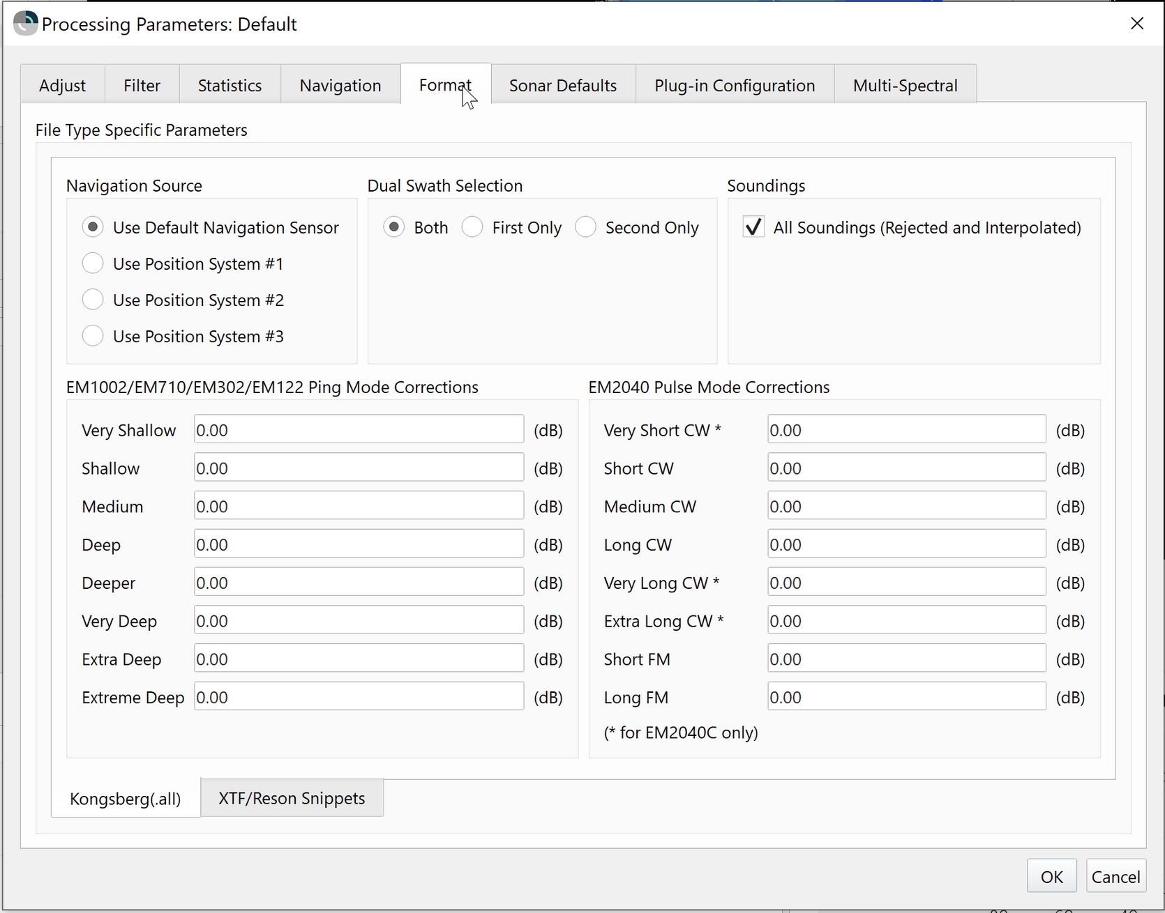
Processing Dialog - .ALL Format Options
Format Options (.XTF)
The specific options for .XTF files as shown in the Processing Dialog - .XTF Format Options figure below, primarily change the source of backscatter (sidescan) and navigation data.
The Navigation source option uses navigation stored in either the Sensor or Ship portion of the standard XTF sonar ping header. By default, Sensor is the selected source.
The Altitude source option allows the altitude value to come from the Ship, Sensor or Auxiliary field of the standard XTF sonar ping header. This value is important as it is used for slant-range correction of the sidescan data. If the Compute Bottom Detection box is checked (Default Setting), the Altitude Source will be ignored.
The Sidescan Data Source option allows selection of sidescan source. This is useful for systems that employ more than 2 channels of sidescan data.
The Compute Bottom Detection option will use a bottom detection algorithm to compute the altitude value for use in FMGT. This field should be checked if the altitude field of the sonar ping header contains a zero value, or if you wish to re-compute the altitude value for use in FMGT.
The Energy Threshold value is used when computing the Bottom Detection. It is a cumulative energy threshold that uses the sum of the energy returned from the seafloor to determine the minimum slant range. A lower Energy Threshold will pick a shallower altitude.
Processing Dialog - .XTF Format Options
Sonar Defaults
The Sonar Defaults tab show in the Processing Dialog - Sonar Defaults figure below provides a means of changing the nominal parameters used for backscatter processing of a specific sonar.
Processing Dialog - Sonar Defaults
These values are used when source files lack proper detailed information. Under normal circumstances, they are overridden by the values in the source files.
The Automatic option means FMGT will automatically select the appropriate default values according to the sonar type information found in the file. These values will then be overridden by data values extracted from the file when they exist. For example, the default pulse length value will be 500 microseconds, but if the file has a non-zero value, such as 50 microseconds, the file value will be used. The dB reference values are always used within the backscatter processing pipeline.
The Custom Defaults option allows the user to specify a custom set of default values. You must either select an entry from the Sonar Type combo box, or create a new entry specific to your needs. For example, if you are creating a custom version of the Reson 7101 default values, simply select the Reson 7101 entry from the Sonar Type combo box. Then click the Copy button to copy these values to a new entry with a new name. You can then change the values directly for this configuration by typing in the text fields. When complete, click on the Apply Edits button. As in the Automatic option, the nominal values will be used when there is a lack of data in the source files. The dB reference values that you have set will always be used.
The Custom Override All option will make FMGT use only the values that you have chosen as sonar defaults. It will disregard the data or sonar type found in the source files. This option is useful whenever you have file that have been either incorrectly logged or incorrectly identified as a specific sonar type.
All of this data is kept in an XML file (Gc_SonarParameters.xml) in the ~./username/FMData folder.
By default, any of the options you select for processing will be used for all lines within the project. If you have data requiring different settings, you can create and set a Settings groups for the designated source files.
Plug-in Configuration
Multi-Spectral
The Multi-Spectral tab allows you to restrict the data processing for pings associated with one particular frequency for sonars that allow for dynamic adjustment of the frequency during acquisition on a ping-by-ping basis. Data products such as ARA, mosaics and statistics will then only represent results from data from the chosen frequency.
Mosaic Parameters
The Mosaic Parameters Dialog as shown in the Mosaic Options figure below is used to control mosaic generation.
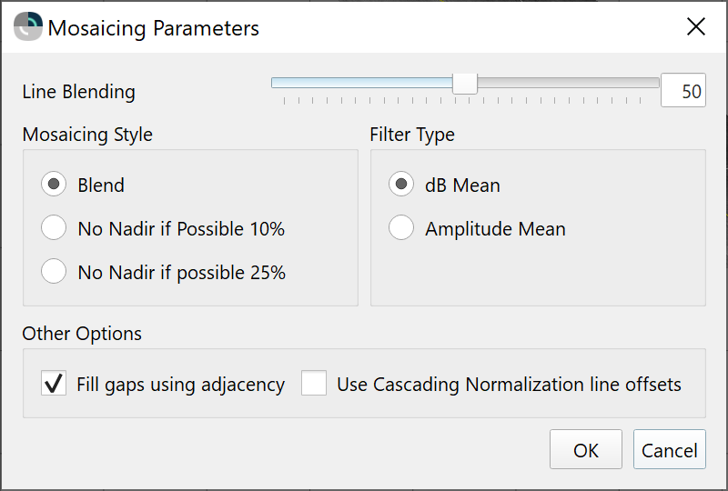
Mosaic Options
The Line Blending option controls how multiple samples that fall within the same mosaic cell are blended. Normally the default is 50% which is an equal contribution from both samples.
The Filter Type options are currently not used by FMGT and will be removed in a subsequent version.
The Mosaic Style options provide control over how pixels are blended in overlapping areas near nadir. Blend is selected by default, where nadir pixels are blended with other overlapping pixels. Using either of the No Nadir options provides two methods of weighting nadir pixels to reduce their effect when you have overlapping data from other lines. If your survey lines do not overlap enough, these options will have no effect on the mosaic. No Nadir if possible 10% will prioritize +-10% of the distance from nadir to the outer beam distance. No Nadir if possible 25% will prioritize +-25% of the distance from nadir to the outer beam distance as shown in the Nadir Blending image below. In both cases, the nadir region is prioritized less.
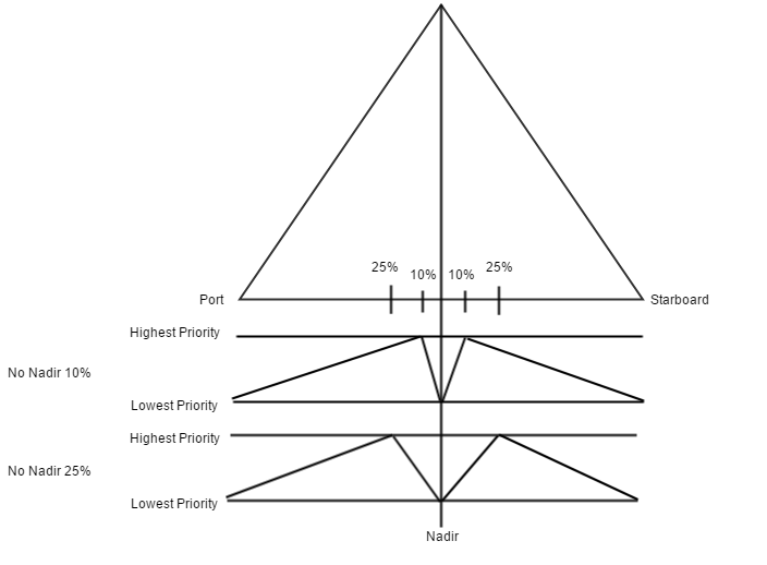
Nadir Blending
The differences between the three mosaic styles can be seen in the images below. Moving left to right, they represent Blend, No Nadir if Possible 10%, and No Nadir if Possible 25%. The last option provides the best results for this survey.
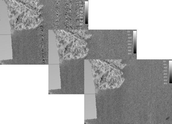
Mosaic Style Options
The Fill gaps using adjacency option will ensure that sequential survey lines don't have a gap between them. This frequently occurs when lines change and the navigation information for a ping exists in the previous or next line. This caused the ping to not be used to generate the mosaic. This option will ensure that FMGT 'looks' in sequential lines to find the appropriate navigation so that all pings are applied to the mosaic. FMGT uses a time window filter to determine when to fill gaps. This value appears in the Navigation tab of the Processing Options dialog. By default it is set to 5.0 seconds.
The Use Cascading Normalization line offsets option is the main control over whether or not dB offsets from the Cascading Backscatter Normalization Tool or the Line Backscatter Adjustment tool are used when mosaicing. When using either of these tools, if the user chooses to save the dB offsets, then this mosaicing option is set by default for the user.
Sensor Configuration
The Sensor Configuration Dialog shown in the Sensor Configuration figure below displays the project sensor configuration. These values are extracted from the first added file and are saved to the project XML file. The user can visualize the values of the sensor configuration here or in the project's XML file.
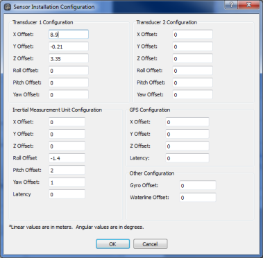
Sensor Configuration
It is important to note that FMGT is expecting to process one sensor type from one vessel configuration within a project. Data from other sensors, vessels or projects may be merged at a later time in Fledermaus.
These values are only for visualization.
The sensor configuration, that is part of the GSF, is used for processing the data.
Project Coordinate System
The Project Coordinate System dialog shown in the Project Coordinate System figure below allows you to view or edit the project coordinate system. If you change the coordinate system, you must re-process all of your data starting with the Coverage portion of the pipeline using the Manual Processing part of the main GUI. See the Manual Processing Tab section for information on manual re-processing of data.
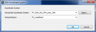
Project Coordinate System
Directory Monitoring
The Directory Monitoring Dialog show in the Directory Monitoring figure below allows FMGT to automatically add files to a defined project. This capability is normally reserved for use during live acquisition. When a sonar file gets added to the specified directory, FMGT will automatically add it to the project, index it, and compute the coverage.

Directory Monitoring
