Digital Terrain Model (DTM) Classes
In Fledermaus, a DTM is a uniformly gridded surface that represents the discrete sampled function z = f(x, y). X and Y are sampled on the uniform grid and Z is the height (or depth) at the specified X and Y coordinates.
SonarDTM
The SonarDTM class allows for the possibility of data holes (called holidays). This is where some of the cells of a uniformly sampled surface are unknown and therefore should not be rendered in the display. The controls for the SonarDTM class are shown below.

DTM Object Attributes
These control how the SonarDTM object is displayed in the Main Visualization Window. The value in the Mesh Gap textfield determines how much the DTM is degraded while moving in an exploration mode. For example, a value of 1 will result in all points being used, and a value of 2 results in every second point being used. The Auto toggle enables the ShiftScapeTM rendering engine to automatically adjust how much the DTM is degraded based on the performance of your computer.
To adjust the Mesh Gap by hand, disable the Auto toggle and enter a value in the Mesh Gap textfield. A lower Mesh Gap means more data is drawn so the screen may redraw slower. A higher Mesh Gap means less data is drawn so the screen can redraw faster. When working with large data sets and the screen is rendering slowly, increase the Mesh Gap and you will be able to move much more easily through the data.
The Transparency slider controls the current transparency value. Dragging the slider right or left will make the DTM more or less transparent, where the right position corresponds to completely transparent and the left position corresponds to completely solid.
When using transparency, note that transparent objects work best when they are drawn last. That is, the transparent object needs to be loaded so that it is the last in the object list. Objects can be re-ordered by dragging and dropping them within the Fledermaus object list. (left-click and drag the object up or down.)
The two toggle buttons change the DTM from a wire frame display to a solid shaded surface Surface Series.
Tools Menu
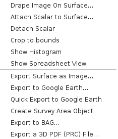
The DTM Tools Menu has items to operate on the DTM, interact with the DTM or export the DTM in another format (below the horizontal rule). Export Surface as Image will export a 2D georeferenced image, in either GeoTIFF format or JPEG with World file. The surface can be exported to Google Earth or to BAG format for import into other software. Export to 3D PDF will export a PDF that can be loaded in Adobe Acrobat Reader or other compatible 3D PDF readers. The surface will be rendered in 3D PDF compatible readers as a 3D object for interactive viewing. Beware that such readers have difficulty loading or rendering surfaces of more than four million cells (2,000x2,000 cells). Crop or reduce the size of the surface before exporting to work around this issue.

Tools Menu

Sample Surface Series
The surface series class is based on the SonarDTM class but adds the ability to store and visualization a set or series of SonarDTM's within a single object. The resulting surfaces can then be animated in time to explore time dependent changes in the surface model. To create a surface series object the SonarDTM objects are generated in the normal fashion. A command line applet called mksurfseries is used to combine multiple SonarDTM objects into a surface series.

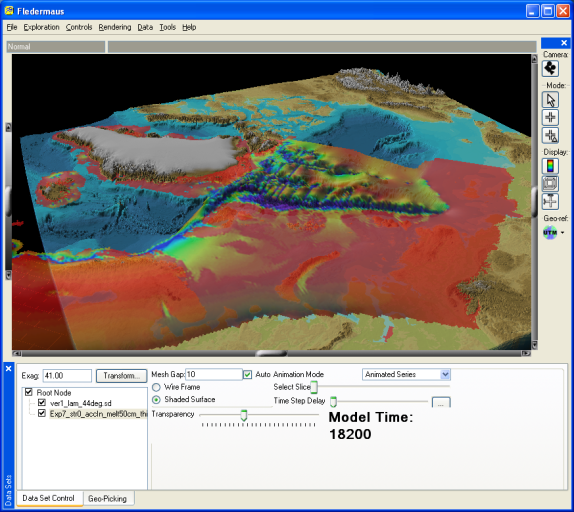
Figure 1 13 - Surface Series Controls
The attribute controls shown in Figure 113 are similar to those of the SonarDTM class with the following exceptions. The Animation Mode popup menu contains two options either Animated Series, or Selected Slice. When Animated Series is selected the visualization will automatically step through the slices one at a time each time the scene is redrawn. Once the last slice is drawn the process repeats from the beginning. When the mode is Selected Slice, the Select Slice slider bar makes it easy to select a given time slice. The Time Step Delay slider controls the speed of the animation. When the slider is at the far left the image will change each frame but as you move it to the right the switch will require more time steps before it changes to the next available image. If the object was assembled with a time reference then a large label will be shown indicating the time step of the displayed image.
Dynamic Surface
Refer to Dynamic Surface Class for more information.
Return to: Reference Manual
