
3DEditor Editor Panels
The Editor Panels are a set of tabs along the bottom of the screen. These tabs are only for advanced editing as most of the editor functionality is contained in the Control Bar and the Right-Click Menu.
Attributes Panel
The Attributes Panel displays a table of all currently selected soundings. This table includes all of the information stored in the PFM file for each sounding. When a sounding is selected in the table, it is displayed in a highlighted color and is also highlighted in the Main Visualization Window. The Attributes Panel is shown in the figure below. To sort the table in ascending or descending order, the headings of the different columns can be clicked with the mouse. Note that to prevent the selected soundings in the Main Visualization Window from changing as the mouse moves, the window can be double-clicked to lock the selection.
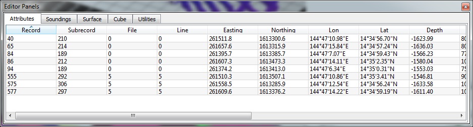
3DEditor Attributes Control Panel
Soundings Panel
The Soundings panel, shown below, allows control of how different soundings are displayed. The Gap text field indicates the point gap used when exploring the surface and the Auto toggle informs the ShiftScapeTM rendering engine to automatically adjust the gap. There are two main sounding classes: rejected and normal (not rejected), as well as three selected sounding classes: suspect, plotted, and feature.
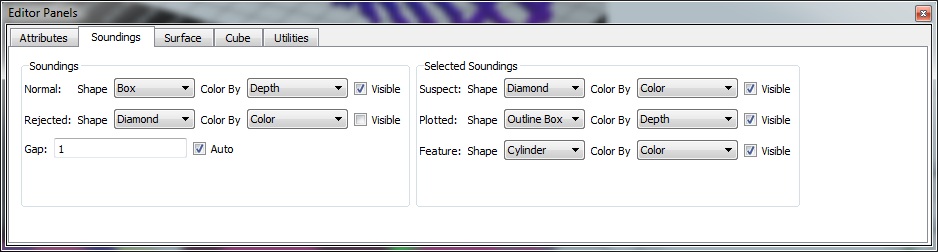
3DEditor Soundings Control Panel
The shape, color, and visibility of each sounding class canbe controlled separately. Each sounding can either be displayed as a box, point, sphere, diamond, cylinder, or outlined box. For large data sets, displaying soundings as points may be faster than the other shapes. A variety of coloring methods also exist including coloring by depth, solid color, record, sub-record, line, file, modified, or checked. Note that if the PFM file contains any additional attributes or flags, they will also appear in this menu and can be used for coloring the surface. Selection of Sounding Shape and Selection of Sounding Shape figures show the pull down menu selections for Shape and Color By. Coloring a surface by line or record makes visualizing which soundings are related much easier. For an example of coloring a surface by line, see the Coloring a surface by Line figure below. The Color By menu in this tab is similar to the Color By menu used in the Control Bar.
If any selected sounding type is marked as invisible, then all points of this type are displayed as normal soundings. To view only those soundings that are marked with a certain flag, turn off the Visible toggle for Normal soundings, and turn on the Visible toggle for whichever selecting soundings you wish to view.
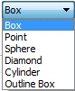
Selection of Sounding Shape

Selection of Sounding Color

Coloring a surface by Line
Surface Panel
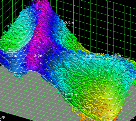
Displaying a smooth surface in the 3D Editor
The 3D Editor is now capable of displaying the surface or DTM that result from a set of soundings as shown in figure Displaying a smooth surface in the 3D Editor. The Surface Panel (figure 3D Editor Surface Control Panel) controls how the surface is displayed. To show the surface, select the Visible toggle or click the Surface toggle in the Control Bar. If the Surface Stalks toggle is enabled, a stalk is drawn from each sounding to the created surface. By default, each surface is drawn via interpolation and thus might not match exactly what is expected. To draw each cell at the exact calculated height, enable the Flat toggle (shown in 3D Editor Surface Control Panel figure). Also, shading is usually applied to the generated surface. At times the shadows can be distracting and can be turned off using the Shade toggle.
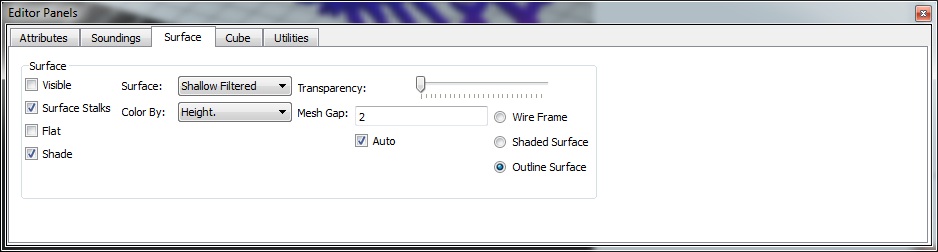
3D Editor Surface Control Panel
The Surface, Color By, Transparency, Mesh Gap, and Auto controls are similar to the Surface Control tab in the main Fledermaus window. See Scientific Data Objects - Visualization Control Panel for more information. One additional option on this tab is to display an Outlined Surface, which is a regular DTM with a white grid laid on top.

Displaying a flat surface in the 3D Editor
Utilities Panel
The Utilities Panel, shown in 3D Editor Utilities Control Panel figure, contains a number of utilities for selecting soundings in the editor. Clicking the Shoal button will select the shoalest sounding in the whole area and clicking the Deep button will select the deepest sounding in the whole area. The Outliers button will select all soundings in a bin that are more than Dist meters away from the average bin height.
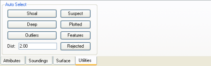
3D Editor Utilities Control Panel
The four buttons on the right side are used to select a set of soundings that have a certain flag set. Clicking the Suspect flag will select all soundings in the editor that have the suspect flag set. The Plotted, Features, and Rejected buttons work similarly for their respective flags. These buttons can be used for a search-and-replace type operation. For example, to change all flags in the display from plotted to feature, click the Plotted button and then on the right-click menu select Edit > Set Feature and then Edit > Clear Plotted.