
Introduction
This How-to will walk through the import of data types from the project dock into Fledermaus 8.
To import data from the external data dock see https://qpssoftware.scrollhelp.site/fledermaus/how-to-external-data-dock
Importing from a project
This section will require a project to be loaded before proceeding.
Step-by-step
Step 1: Importing Raw Sonar Files to surface
-
In the project window right click on the Raw Sonar Files and select 'Create Surface from Points...'
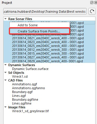
Figure 1: Create Surface option
-
The Data Gridding window will launch
-
Check that the Import co-ordinate reference system is correct and click Next
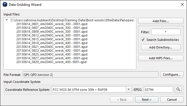
Figure 2: Data Gridding Wizard, input Files
-
Set the output coordinate if it is different from the input coordinate system
-
Select the gridding parameters required for your surface, including the cell size, gridding type and file name.
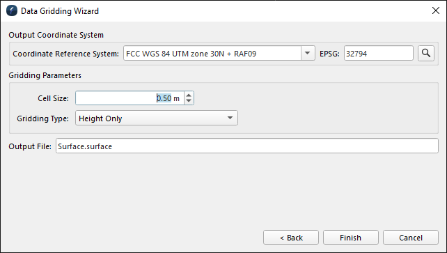
Figure 3: Data Gridding Wizard, gridding options
-
Click Finish
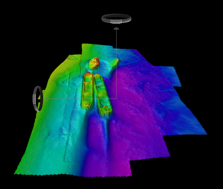
Figure 4: Imported Grid
Step 2: Importing Raw Files as Points
-
In the project window right click on
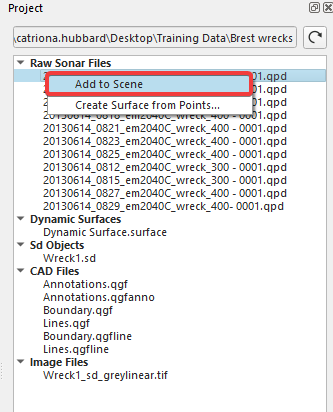
Figure 5: Project window, add to scene
-
The point file(s) will be loaded to the scene
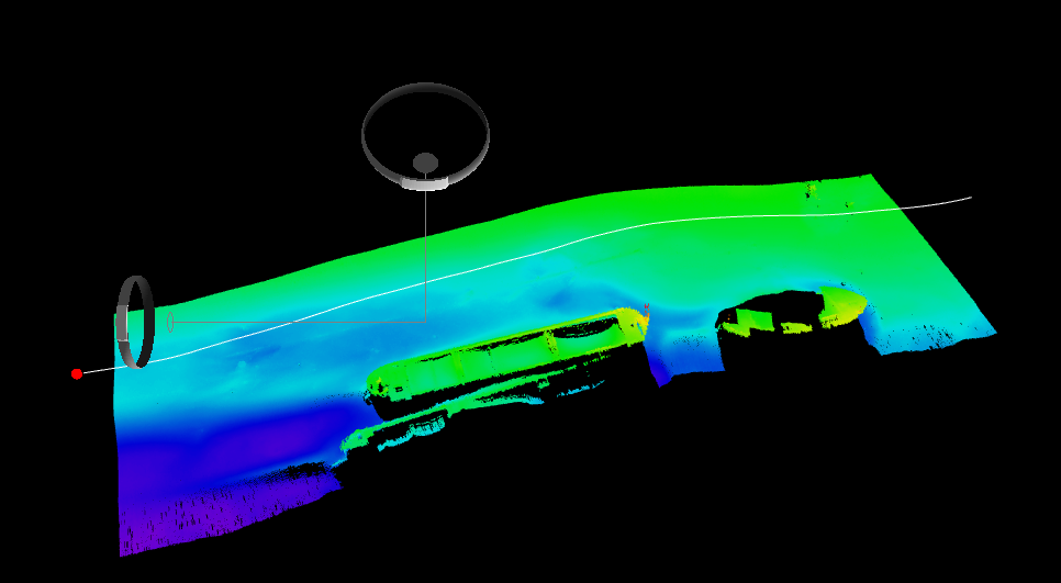
Figure 6: Loaded .points file
Step 3: Importing Dynamic Surface
-
Right click on the Dynamic Surface in the Project window and select 'Add to Scene...'
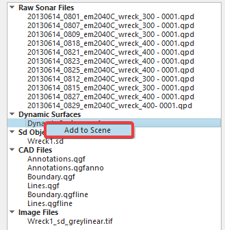
Figure 7: Load Dynamic Surface
-
The Dynamic Surface will be loaded to the Scene
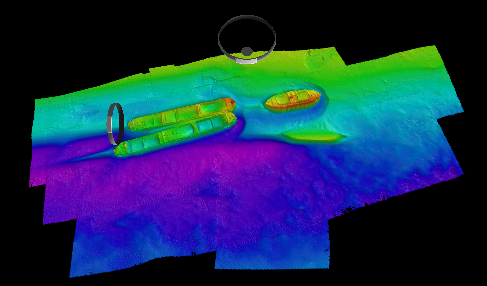
Figure 8: Loaded Dynamic Surface
Step 4: Importing SD Objects
-
Right Click on the SD object(s) and select Import into Scene
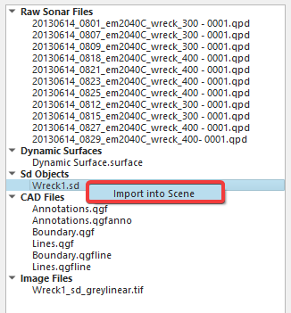
Figure 9: Project window, load SD files
-
The SD file will need to be upgraded. Select the Load Object(s)
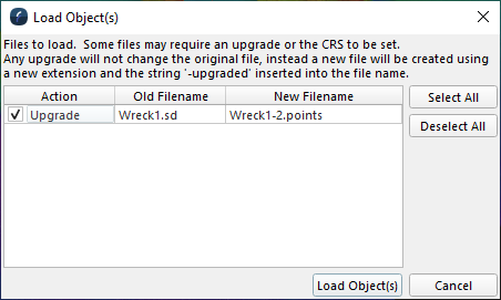
Figure 10: Upgrade objects window
Step 5: Importing CAD Files
-
Right Click on the CAD file and select 'Add to Scene'
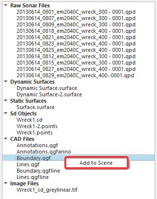
Figure 11: Add CAD files to scene
-
Ensure that the coordinate reference system is correct if required and select Load Object(s)
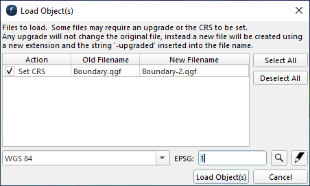
Figure 12: Load Objects window
-
The line object will then be loaded to the scene.
Step 6: Importing Image
-
Right click on the image file to load
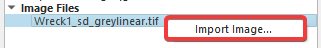
Figure 13: Load Image file
-
Check that the file name, geodetics and bounds are correct
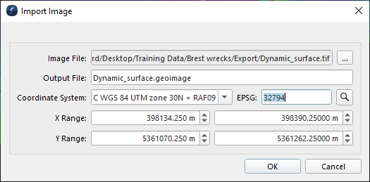
Figure 14: Import Image dialog
-
Once happy, click OK to load the image file to the scene.