
Create Static Grid Dialog
How to Start
-
Scene Objects Dock → Right-Click on Object → Operations → Create Static Grid
-
Scene Objects Dock → Operations→ Create Static Grid from Point Files
What it Does
The Create Static Surface option allows the user to create a uniformly gridded surface with a specified grid resolution from selected point files with specified settings. Many different point files from ascii, to multibeam formats such as Qpd, and .all, to Lidar (.las, .laz) are supported here. The result will be a .staticgrid file and object type.
General Description
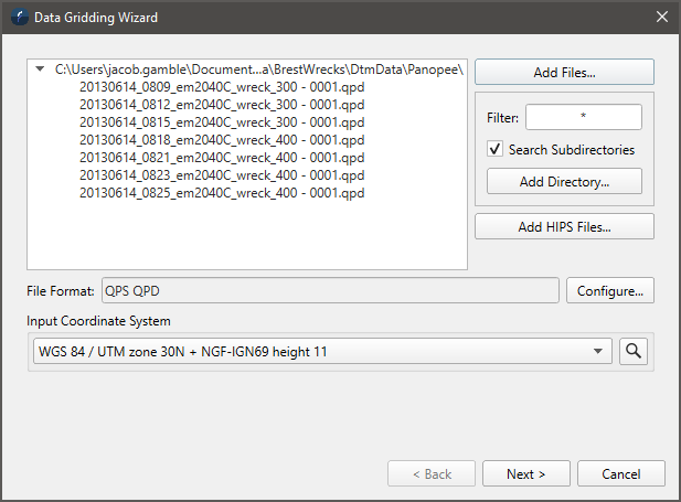
This wizard has two pages. The first page is used to select the source files that contain point data that one wants to produce a gridded surface for, and the second page contains the options used in the production of the gridded surface product. In the 1st page shown above the main area is used to show the selected files. Along the right hand side are the options to select these files to grid. The Add Files button opens a standard file selection dialog to locate and select one or more files. One can do this multiple times to add as many files as is desired. The 2nd way to add files is by scanning a directory and optionally sub-directories and adding all the files that match a certain pattern. For example if you set the filter to *.all and click the Add Directory button, one will be asked to select the directory and any files found that match the pattern will be added. The 3rd method to add files is used when you are gridding files from a CARIS HIPS project.
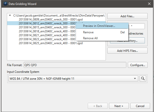
You can remove files from the list by right clicking to see to popup menu or you can just remove files by selecting them and hitting the delete key. One can also preview the contents of a particular file using the Preview in OmniViewer option which runs OmniViewer and loads the selected file.
Below the file list it will show the format type detected and for some formats like ascii you can use the configure button to select which columns to grid or apply invert operations on the data as it is read. Finally it is important to specify the coordinate system of the input files. For formats that store a coordinate system like QPD this will be set automatically but if one has an ascii file for example one will need to identify the coordinate system manually. Once the input files are selected and the coordinate system of them set click the Next button to move to the gridding options page.
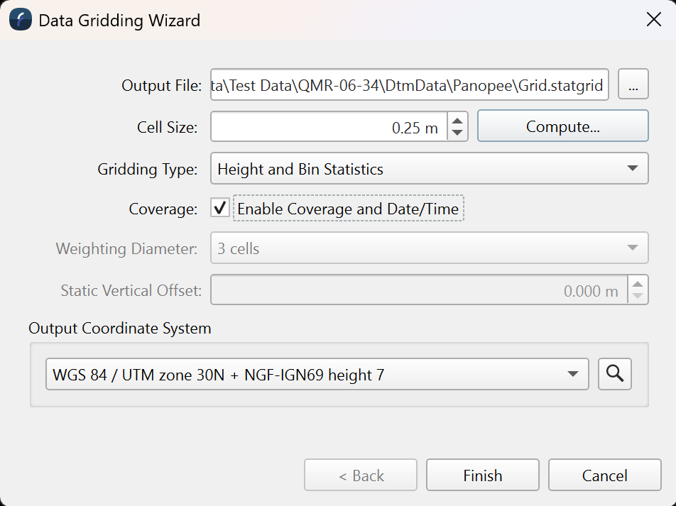
The first option on this page is the output directory. One then needs to select the cell size of the grid one wants to produce along with the grid type to be made. The compute option will produce a suggested cell size based on the size of the source files added on the previous page. The default gridding algorithm is a weight moving average. This builds a static grid with just height data but the input points are smoothed across multiple cells based on the weighting diameter specified.
If the selected gridding type is set to either Height only or Height and Bin Statistics then the Coverage option will become available, this will allow you to color your grid by the number of survey lines that the cells have data from and also allow coloring by date/time data that the grid possesses.
The default Weighting Diameter will be three cells means if the cell size is .25 or 25cm then each point will have a 75cm area of influence that falls off as you move away from the points actual location. A weight diameter of 3 is a very good option to produce high quality surfaces with not too much smoothing. The weight diameter must always be an odd number and higher number mean more smoothing is applied to the data. A weight diameter of 1 means only the cell the point falls in will be affected. This grid type also allows one to specify a Static Vertical Offset for special occasions when one might want to add a vertical offset to every point being gridded. If will effectively shift the produced surface up or down by the specified amount. Only the WMA grid type supports a static vertical offset. There are two other grid types as shown in the popup below. The final option on this page is to specify the output coordinate system of the grid to be made. By default it will be set to match the coordinate system of the input files but it is possibly to reproject the point data by selecting a different output coordinate system.
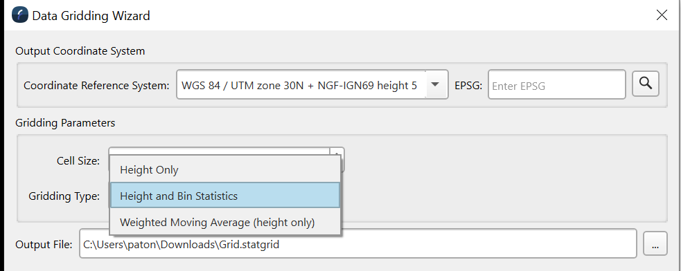
The Height Only type produces a static grid where the height is computed by averaging only the points that fall in a given cell. No weighting is applied and the resulting surface like the WMA type above only contains height data. The Height and Bin Statistics option also only averages the points that fall within each cell but the resulting static grid contains extra information that can be visualized including the point count per bin and the standard deviation of the surface cells.
Once the options are set and an output file is provide click the Finish button to start the process of producing the gridded data product.
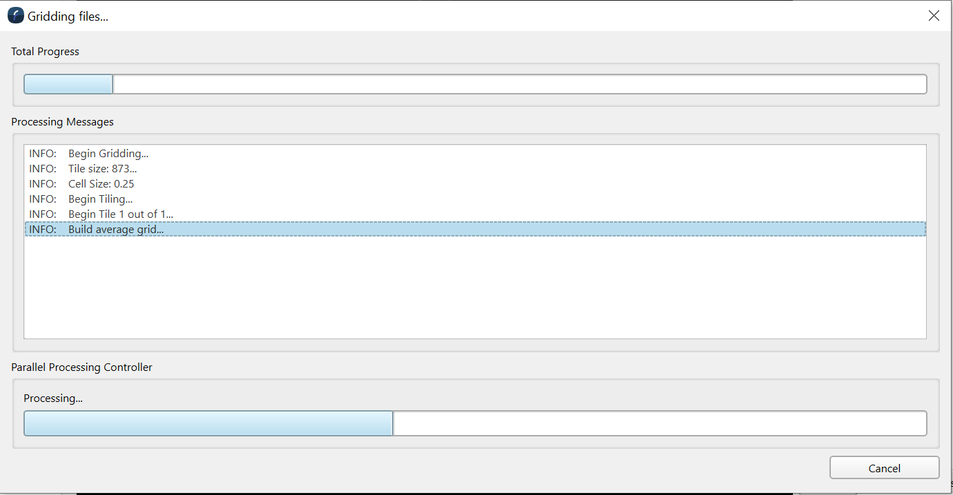
One will see the above dialog as the surface is being produced and all the specified input files are used to construct it. Once complete the surface will be loaded into the 3D scene.