Tritech Gemini (Forward Looking Imaging Sonar) - 47
Description
Driver to decode data from a Tritech Imaging Sonar.
The following imaging sonar products are supported by this driver:
Gemini 720i
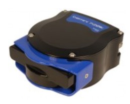
Gemini 1200i
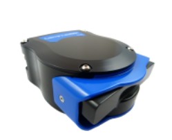
Driver Information
Driver | Tritech Gemini (Forward Looking Imaging Sonar) | Interface Type | SDK | Driver Class Type | Freebase |
|---|---|---|---|---|---|
No | Input / Output | Input/Output | Executable | DrvFLSControl .exe GEMINI | |
Related Systems |
| ||||
System Interfacing
Notes
This driver is using Tritech's SDK to communicate with the imaging sonar unit.
There is a known issue that this SDK only allows to have one instance accessing the sonar unit.
That means that you can not run Tritech’s Gemini Evo software simultaneously with Qinsy on the same computer.
Database Setup
Add a Forward Looking Sonar to your template setup and select driver “Tritech Gemini (Forward Looking Imaging Sonar)“.
Wizard Page 1
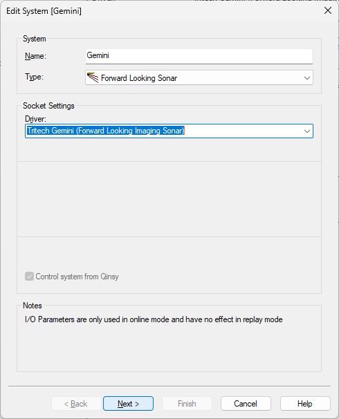
There are no interfacing parameters required.
When going online the driver will automatically try to make a TCP network connection in the background with the sonar computer.
Of course this computer must be on the same network as the Qinsy computer.
The sonar system can be controlled using Qinsy while being online (see chapter Online).
Wizard Page 2
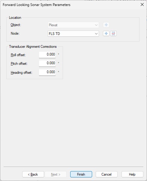
Select the correct node location where the imaging sonar is mounted
The transducer alignment corrections are currently not used so you may leave the three values to zero.
Online
Controller
When on-line, the imaging sonar unit can be (limited) controlled using the Controller.
Select Echosounder Settings, click on the Forward Looking Sonar System icon, and select the 'Control' tab page.
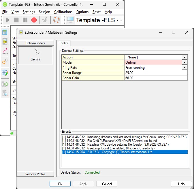
First of all make sure that the Device Status in the bottom pane of the dialog says ‘Connected’.
This status should always be ‘Connected’ regardless of the selected Mode (Off, Online and/or Replay).
Note that when the status is ‘Not Connected’ you could try the ‘Reset System I/O’ option from the Controller’s pull-down menu.
Action | Note that a change of action will be applied immediately so using the dialog Apply or OK button is not necessary. The selection will always revert back to [ None ] after each selected action.
|
Mode | Note that a mode change will be applied immediately so using the dialog Apply or OK button is not necessary.
|
Ping Rate | Select a fixed interval for pinging the sonar unit or set the unit in free running mode.
Note that the actual ping rate is limited by range settings |
Sonar Range | Set the sonar range in meters Valid ranges are 1m - 150m |
Sonar Gain | Set the sonar gain as percentage Valid values are 1 - 100 percent |
Log File (GLF) | Enter the full path and filename of the GLF file for replay, which will start immediately when the file exist. This setting is only visible in Replay Mode Tip: when the replay has ended the playback can be restarted by changing the Mode to Off and then back to Replay again. |
Displays
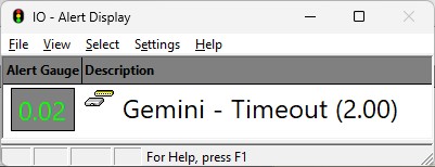
Alert Display
An Alert Display is useful to see if data is coming in regularly at the I/O port.
Therefore it should be the first display to check when going online.
Observation Physics Display
An Observation Physics Display is also useful to monitor if incoming imaging data is decoded successfully and at what update rate.
Further use the additional columns to monitor some meta data values that comes with the decoded imaging data.

Columns
Raw
A text label with the manufacturer’s SDK version being usedQuality
The size in bytes for the entire ping image updateParameter 1
The current sound velocity used by the sonarParameter 2
Incrementing ping numberParameter 3
Always a fixed value of 7201200
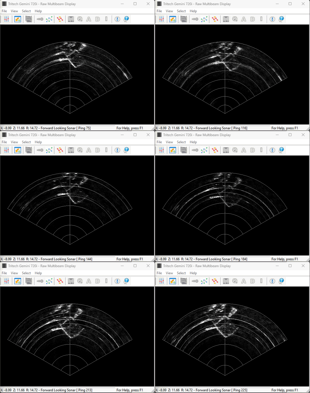
Raw Multibeam Display
Use this display to visualize the imaging data.
Use the View Properties dialog to change some specific Forward Looking Sonar settings:
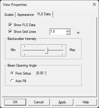
Note that settings from the other tab panels have no effect when using a forward looking sonar system.
