
Description
The idea behind this driver is to decode Multibeam, Position, Motion and Heading data from another Qinsy setup.
This could, for example, be used when you have a main vessel and one or more ASVs.
This driver can then be added to the main vessel's Qinsy setup so you can monitor the coverage of the ASV in combination with your own coverage.
For outputting the Multibeam, Position, Motion and Heading data, you can use the "DTM Socket Output" option which is available from the Qinsy Controller.
Qinsy setup information related to input can be found in the Qinsy Config tab.
Qinsy online setup related to output can be found in the Qinsy Online tab.
This driver should only be used to monitor the coverage as the received footprints will shift about 2cm in any direction. Do not use this driver to record the primary database, grid or QPD.
Driver Information
|
Driver |
Network (UDP) - QPS Binary - Coverage Monitoring (UTC) |
Interface Type |
UDP |
Driver Class Type |
Counted |
Created |
|
|---|---|---|---|---|---|---|---|
|
UTC Driver |
Yes |
Input / Output |
Input |
Executable |
DrvQPSCountedUDP.exe QINSY_DTM_BINARY PPS |
Updated |
|
|
Related Systems |
|
||||||
Qinsy Configuration
In order to use the Coverage Monitoring functionality you need to have Qinsy instances: the "main/monitoring" vessel and the "remote" vessels.
Template Monitoring vessel
In the template of the monitoring vessel the user needs to configure multiple objects.
For each remote vessel a separate object needs to be configured.
Object - Main Vessel
On the main vessel the systems of the vessel need to be configured according to the other driver manuals.
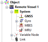
Object - Remote Vessel
On the remote vessel it is advised to use the same vessel shape and node offsets as in the Qinsy instance on the main. The following systems can be interfaced.
Tip
Use the 'Related System' wizard for quick interfacing.
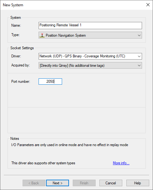
Position Navigation System
For the positioning of the remote vessels the user should add a Positioning Navigation System with the driver for Coverage Monitoring.
The Port number should correspond with the port number that is used in the DTM Socket Ouput from the Qinsy remote.
On the second page of the wizard the correct node should be selected and the Horizontal/Vertical Datum should be set to the local datum.
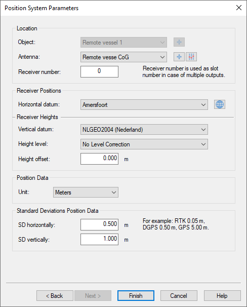
The DTM Socket Output will send positioning data that is valid for the Multibeam Node of the vessel.
This means that in the template of the monitoring vessel the node for the positioning system of the remote vessel should be set to the Multibeam node as well.
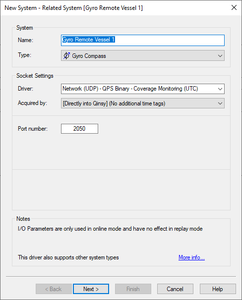
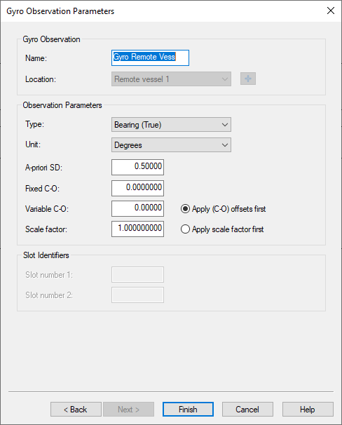
Gyro Compass system
For the Gyro system the user should add a Gyro System with the driver for Coverage Monitoring.
The Port number should correspond with the port number that is used in the DTM Socket Ouput from the Qinsy remote.
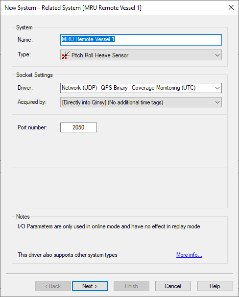
Pitch Roll Heave System
For the motion of the remote vessels the user should add a Pitch Roll Heave Sensor with the driver for Coverage Monitoring.
The Port number should correspond with the port number that is used in the DTM Socket Ouput from the Qinsy remote.
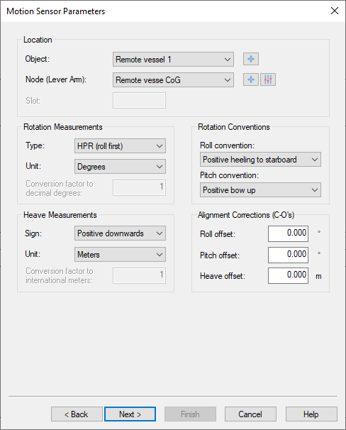
On the second page of the wizard the correct configuration should be set:
-
Correct Node (MBES location of the remote vessel)
-
Conventions
|
Roll |
Positive heeling to Starboard |
|---|---|
|
Pitch |
Positive Bow up |
|
Heave |
Not decoded |
Multibeam Echosounder
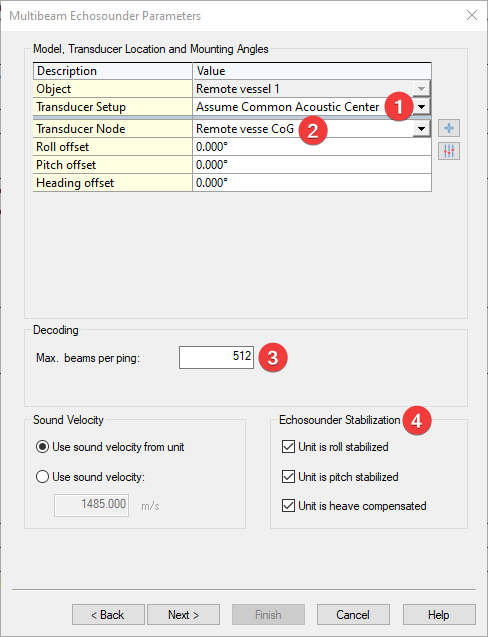
For the Multibeam data of the remote vessels the user should add a Multibeam Echosounder with the driver for Coverage Monitoring.
The Port number should correspond with the port number that is used in the DTM Socket Ouput from the Qinsy remote.
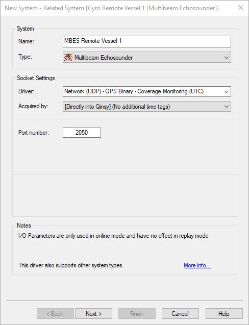
On the second page of the wizard set up the following items:
-
Assume Common Acoustic Center
-
Select the node of the MBES
-
Max. beams per ping should correspond with the number set in the multibeam system in the template of the remote vessel
-
The Echosounder Stabilization should be turned on if a Pitch Roll Heave Sensor is interfaced
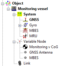
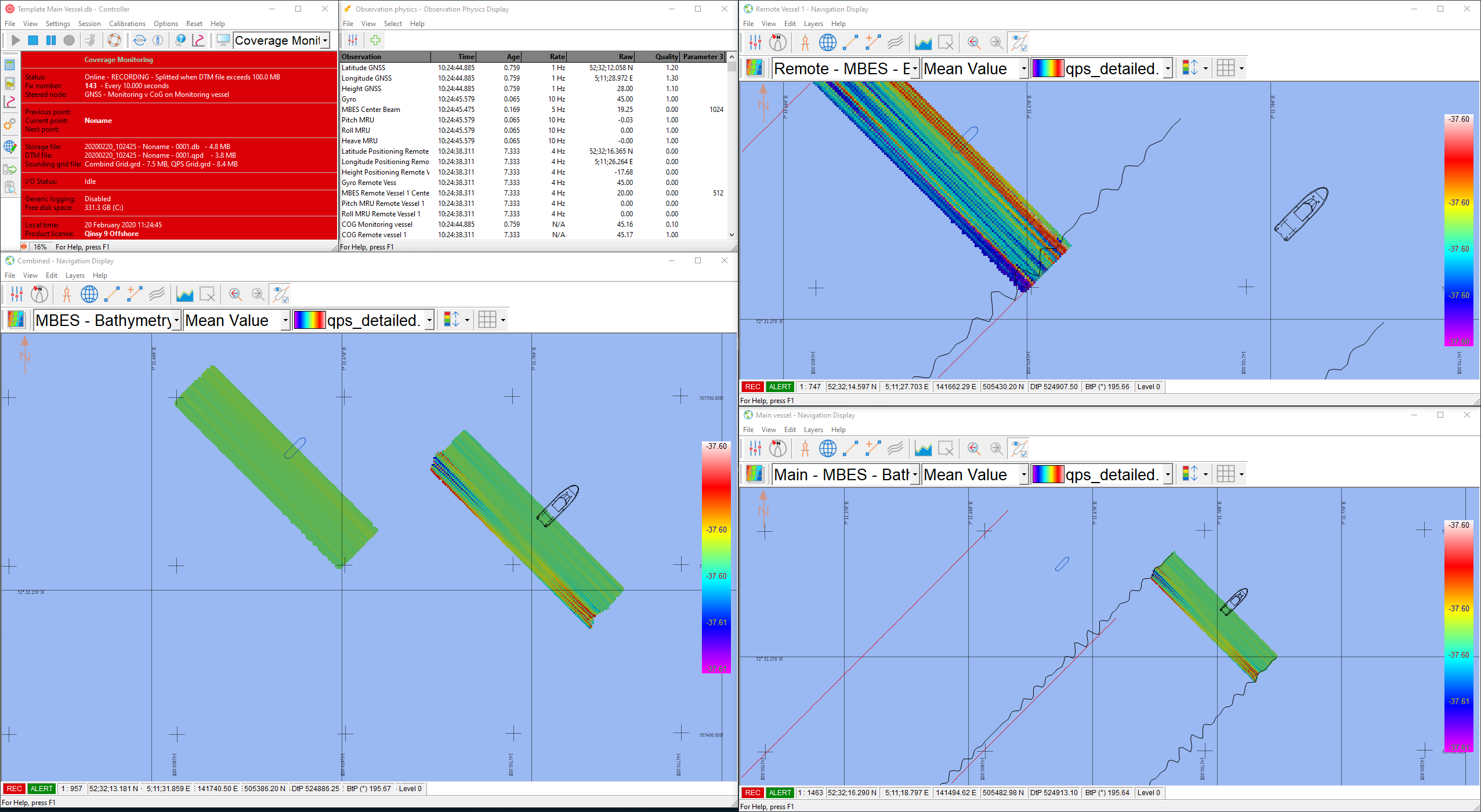
The Qinsy Template on your main vessel should now look similar to this:
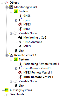
In case you have multiple Remote vessels, they can be added in the same way to this template.
Template Remote Vessel
On the Remote vessel the systems of the vessel need to be configured according to the other Driver Manuals of the specific systems you have interfaced there.
For more information on which driver you should use, please have a look at our Equipment Space.
Qinsy Online
Monitoring Vessel
The following displays can be useful to monitor the swath coverage:
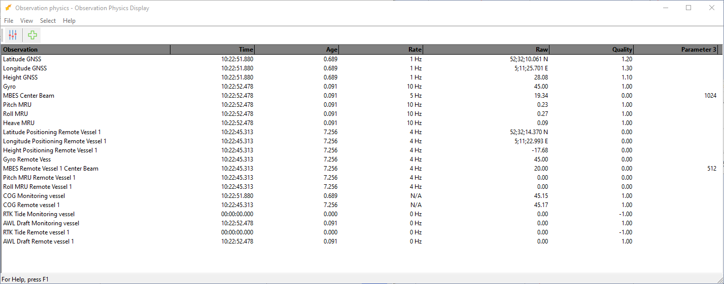
Observation Physics display
With the Observation Physics Display, the connection can be monitored in order to check if the data from the remotes is still coming in.
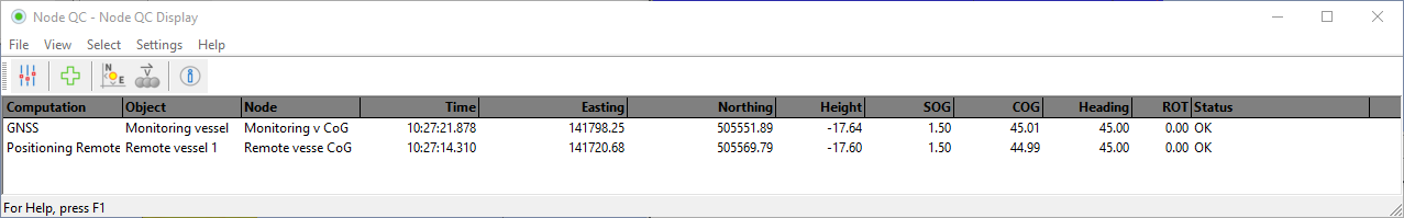
Node QC Display
Monitor the Node QC Display to make sure the objects are still calculated in the computation.
Navigation Display
Monitor the Swath Coverage with the Navigation Display.
Remote vessel
On the remote vessel the user can set up the displays if needed.
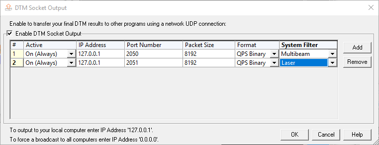
To send the data from the remote to the Main vessel, the DTM Socket Out needs to be configured:
-
Go to Options - DTM Socket OUT and enable the output
-
Make sure the IP Address is set to the remote
-
Make sure to set up 1 system per port in case you would like to send over multiple systems
-
-
Packet size can be changed to what the user prefers. We don't have a recommended size for this
-
The Output format is QPS Binary
For more information about the DTM Socket Out press F1 to open its Help files.
To process the data from the remote vessel in a later stage, the vessel should record its own Databases and QPD's.