
Description
This driver is used to decode the iXblue proprietary NMEA message which starts with $PHOCT.
This message is outputted by the iXblue:
-
Octans - Motion & Heading
-
HydrINS
-
PHINS
-
LandINS
-
RovINS
Motion and heading are decoded depending on the selected/entered slot value(s).
Apart from the Motion: roll, pitch, heave and Heading observations the driver decodes the following additional (miscellaneous) observations:
-
surge
-
sway
-
heave
-
speed
-
surge
-
speed
-
sway speed
The additional observations are decoded by a Miscellaneous System.
The Heave for the TAH message can also be used as an alternative depth source when using a Fall Pipe ROV.
Driver Info
Coding Notes
Decoding Notes
All fields are decoded, except for the latency field. The latency should be entered manually in Database Setup. No unit conversions are being applied by the driver. While decoding the header, version and checksum field (may be disabled) are being checked for valid data. In case the header field does not match the required value the whole message is rejected. In case the version field does not match the required value the whole message is rejected. In case the computed checksum does not match the checksum in the message the whole message is rejected. The status field values are translated into quality indicator values as follows:
|
Status Value |
Quality Indicator Value |
|---|---|
|
T = Valid |
1.0 |
|
E = Invalid |
-1.0 |
|
I = Initializing |
-2.0 |
See Online chapter regarding an Alert display
Timing (UTC driver)
When using the UTC driver and the system is not receiving the Time Synchronization pulse and the time message every second, the unit will report an invalid flag for timing.
Network Driver without (UTC)
The network driver without (UTC) identification may only be used in setups where timing of motion is not critical. This driver should not be used when doing survey grade data acquisition.
The Timestamping of network messages is unreliable due to dynamic latency on network infrastructures.
System Interfacing
Interfacing Notes
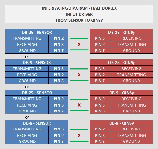
In case data is transmitted to Qinsy via serial cable, only one-way cable wiring is needed, using the following wiring diagram:
Qinsy Config
System Configuration
In order to allow the sensor to output lever arm corrected values of several of the outputted observations the user should enter the offsets of the sensor with respect to the Center of Gravity (CoG) of the object on which the sensor is mounted.
This may be done using the iXblue repeater software or the WEB interface, if applicable. This software may also be used to set the baud rate at which the sensor outputs the NMEA messages as high as possible.
Entered in iXblue sensor
-
Offset with respect to CoG (Qinsy)
-
C-O Heading
-
C-O Pitch
-
C-O Roll
-
Output lever arm = CoG (Qinsy)
-
The actual / approximated position.
Please connect your GNSS (GPS/GLONASS) to the iXblue sensor and feed it with $GPGGA and $GPVTG.
If it's not possible to connect a GNSS system to the unit (i.e. ROV), one needs to enter the approximate position into the Ixsea sensor.
Timing
-
ZDA
Please note that if the IxSea sensor is interfaced with Time Synchronization and $xxZDA, the ZDA string needs to end at the precise second i.e.$GPZDA,HHMMSS.ss,dd,mm,yyyy,xx,yy*CC<CR><LF>
$GPZDA,201530.00 ,04,07,2002,00,00*60<CR><LF>The above is at the moment mandatory for Octans systems and other systems with old firmware. Please contact iXBlue for more information.
-
Trimble UTC
When a Trimble is used, the Trimble UTC message is preferred:UTC yy.mm.dd hh.mm.ss ab<CR><LF>
UTC 11.05.10 14:53:26 59<CR><LF>The UTC message does not contain a fraction for seconds like the $xxZDA, therefore the time message complies with the time of the pulse.
See Drivers manual: "Trimble UTC" for more information about the pulse and time message.
Database Setup
The driver supports the following system types:
|
System type |
Observation |
|---|---|
|
Pitch, Roll and Heave Sensor |
Pitch, Roll and Heave |
|
Gyros and Compasses |
Heading |
|
Underwater Sensor |
ROV Depth |
|
Miscellaneous Systems |
Generics (Heave, ROT, Surge, Sway) |
All above systems can be used on the same COM / UDP port. This means that you only need one COM / UDP port to interface the above observations (Motion, Heading and Miscellaneous).
The $PHOCT message from the Ixsea sensor is decoded by the driver, but the fields to be used from the string depend on the selected slot value in the driver setup pages.
Pitch, Roll and Heave Sensor
-
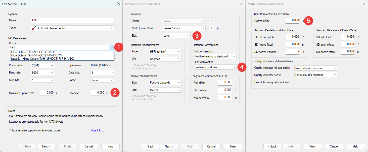
Item number 2 and 5 are only applicable if you selected “iXblue Octans TAH ($PHOCT) R-P-H” since we use the time of arrival.
The other two are UTC drivers meaning that we decode the time from the message and use that. -
We know the latency for some systems:
-
Octans Generation 3: 0.025 sec
-
Octans Generation 4: 0.003 sec
-
-
We suggest to setup the Lever Arm in the Octans so it outputs the Pitch/Roll/Heave for the Center of Gravity (CoG) location.
In that case, select Lever.-
Select Raw in case you want to decode the Pitch/Roll/Heave which is valid for the location of the sensor itself.
-
More info on this below.
-
-
The convention for this format is Positive bow down. This is different from the Qinsy convention.
-
This is the same as the Latency but then inverted.
-
Octans Generation 3: -0.025 sec
-
Octans Generation 4: -0.003 sec
-
For a single sensor of the 'Pitch, Roll and Heave Sensor' type the following slot values apply:
|
Slot value |
driver |
Decoded fields |
|---|---|---|
|
Raw |
Serial / Network |
Roll (field 8 & 9), Pitch (field 10 & 11) & Raw Heave (field 12 & 13) |
|
Raw1 |
Network |
|
|
Raw2 |
Network |
|
|
Raw3 |
Network |
|
|
Slot value |
driver |
Decoded fields |
|
Lever |
Serial / Network |
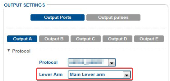
Roll (field 8 & 9), Pitch (field 10 & 11) & Heave (field 13 & 14) Check the selected Lever Arm (Primary or Lever A/B/C) in the iXBlue output setup (see picture below).
|
|
Lever1 |
Network |
|
|
Lever2 |
Network |
|
|
Lever3 |
Network |
If a network driver is selected the $PHOCT string is sent to Qinsy by UDP.
It is possible to use the UDP input on multiple objects by selecting different slot numbers e.g.:
-
Object 1 -TAH driver - Slot value: Lever1
-
Object 2 -TAH driver - Slot value: Lever2
-
Object 3 -TAH driver - Slot value: Lever3
This allows for multiple PRH and gyro systems to use the same output string from the system.
If the slot number is not kept unique then for some systems no data will be decoded.
Replay both Lever and Raw heave values
If you want to be able to Replay the data with the Raw and Lever slot values then you need to add 2 Systems on a single object:
-
TAH driver - with slot value Lever.
-
TAH driver - with slot value Raw.
You should be able the use the same UPD port.
If you are using a serial cable you will need to split the cable to a second Com port.
Gyros and Compasses
For the 'Gyros and Compasses' type the following slot value applies:
|
Slot value |
driver |
Decoded fields |
|---|---|---|
|
Heading |
Serial / Network |
True heading & status (field 6 & 7) |
|
Heading1 |
Network |
|
|
Heading2 |
Network |
|
|
Heading3 |
Network |
|
Underwater Sensor (Heave as Depth when using a Fall Pipe ROV)
For the 'Underwater Sensor' type the following slot values apply for an 'ROV Depth' observation:
|
Slot value |
Decoded field |
|---|---|
|
HeaveRaw |
Raw heave (field 12) |
|
HeaveLever |
Heave (field 14) |
Heave as Depth
Make sure that you set the scale factor to: -1.00
Miscellaneous Systems
For the 'Miscellaneous Systems' type the following slot values apply:
|
Slot value |
Decoded field |
|---|---|
|
HeaveRaw |
Raw heave (field 12) |
|
HeaveLever |
Heave (field 14) |
|
SurgeLever |
Surge (field 15) |
|
SwayLever |
Sway (field 16) |
|
HeaveSpeed |
Heave speed (field 17) |
|
SurgeSpeed |
Surge speed (field 18) |
|
SwaySpeed |
Sway speed (field 19) |
|
HeadingROT |
Heading rate of turn (field 20) |
The observations decoded by the Miscellaneous Systems driver are only recorded and can be:
Shown in a Generic Display,
Logged to a online logging file (Generic Logging)
Exported by Generic Export
Info
All slot values from the 'Miscellaneous Systems' use the 'Heave status' field (field 13) as the source for the observation's quality indicator value.
-
ALL SLOT VALUES ABOVE ARE CASE-SENSITIVE
-
No duplicate slot values allowed
E.g. if you have defined an ROV Depth observation with slot value 'HeaveRaw', you should not use this slot value again for a Miscellaneous Generic observation.
Qinsy Online
Online
Users are advised to set up an Alert Display to prevent the user from logging data with invalid motion and heading data.
Minimum required alerts would be the ones on the quality flags:
When users are using INS systems they are advised to to check the standard deviations of the Pitch, Roll and Heading.
This can be done in the iXSea User Interface:
-
Repeater program on the Expert Display
-
Web interface on the Navigation display/page
Read their iXSea manuals regarding the INS initialisation procedure.
Qinsy Processing
Post Processing (INS)
If an iXSea INS system is used, RAW data can be logged.
The RAW data can be Post Processed with POPINS or DELPHINS. The software can use a Post Processed GNSS trajectory as an improved position input to aid the INS.
With or without this improved position trajectory the software will process the data in forward and backward direction, which improves the INS position trajectory.
The result file can be imported into the recorded Qinsy *.DB file. This can be done within the Raw Data Manager (Replay).
POPINS and DELPHINS software allow the user to replace the recorded GNSS input data with a post processed GNSS trajectory.
This post processed trajectory will function as an improved position input for the INS, which can reduce the GNSS rejected positions and reduce the INS drift (periods).
Please note that Qinsy does not record RAW GNSS data for Post Processing purposes.
RAW GNSS data should be recorded from the GNSS separately (see picture above).
When setting up a template database for PP purposes, it is advised to add extra systems to your database as shown above.
LANDINS Embedded data logger records:
-
INS realtime computed values at 5Hz. (All repeater data, H,R,P, STD etc.)
-
All RAW Data of ACC and FOG
-
All ODO DATA, as received from ODO realtime
-
All GPS DATA, GGA, GST, as received from GPS realtime or Qinsy's - NMEA conditional output driver
-
Up to 3 EVENT MARKERS
Additional Info
Drivers.io Notes
The following command line options may be added to the "Drivers.io" file:
|
Option |
Description |
|---|---|
|
NOCS |
Disable checksum validation |
|
PPS (Time Synchronization) |
Enable decoding of UTC time field (disables driver time tagging) |
Message Note
Although the NMEA message which is decoded by this driver is terminated by a CRLF pair the driver requires a fixed number of characters per message to determine the end of the message.
Using this end of message detection mode allows the driver to perform more accurate time tagging than when the CRLF pair had been used to detect the end of message.
Network - iXBlue Octans TAH (PHOCT) (UTC) - 23