
Description
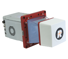
Driver to control and decode the real-time data-stream from a RIEGL miniVUX-HA, an extremely lightweight and compact highly accurate laser scanner.
This laser scanner is part of RIEGL's miniVUX Series to which the miniVUX-1UAV² and miniVUX-3UAV scanner also belongs.
Note that this driver only supports the miniVUX-HA scanner.
Please contact QPS in case you need support for the other members of the miniVUX Series.
Driver Information
System Interfacing
Click here to expand interfacing details...
Network
Communication with the scanner always goes via TCP network.
Due to the enormous amount of data to be expected it is required to use a fast (Gigabit) network card.
Before commencing your online scan operation it is good to check the network connection between your computer and the laser scanner. The best way to do so is to access the scanner’s built-in WebGUI by using a web-browser .
Another advantage of the WebGUI is to quickly verify if the scanner is accepting the accurate time message and pulse.
See below paragraph WebGUI for details.
Timing
Without time-synchronization the driver will time-stamp the data when received at the network port.
However, due to network characteristics in general this may result in inaccurate timing, especially when you are scanning from a moving platform (vessel or car).
Therefore timing via Time Synchronization pulse (PPS) from a GNSS system is mandatory.
Your scanner needs to be interfaced directly to a GNSS receiver outputting a pulse (PPS) and a time message every second.
The GNSS led on the rear panel should be steady & colored green. Or use the GNSS page in the WebGUI to check if time and/or pulse is accepted or not:
WebGUI
You could use a standard web browser in order to communicate directly with the scanner and verify some initial settings.
Enter the IP address of the scanner in the address bar of the browser (in this example http://192.168.0.128/) and the following page should appear:
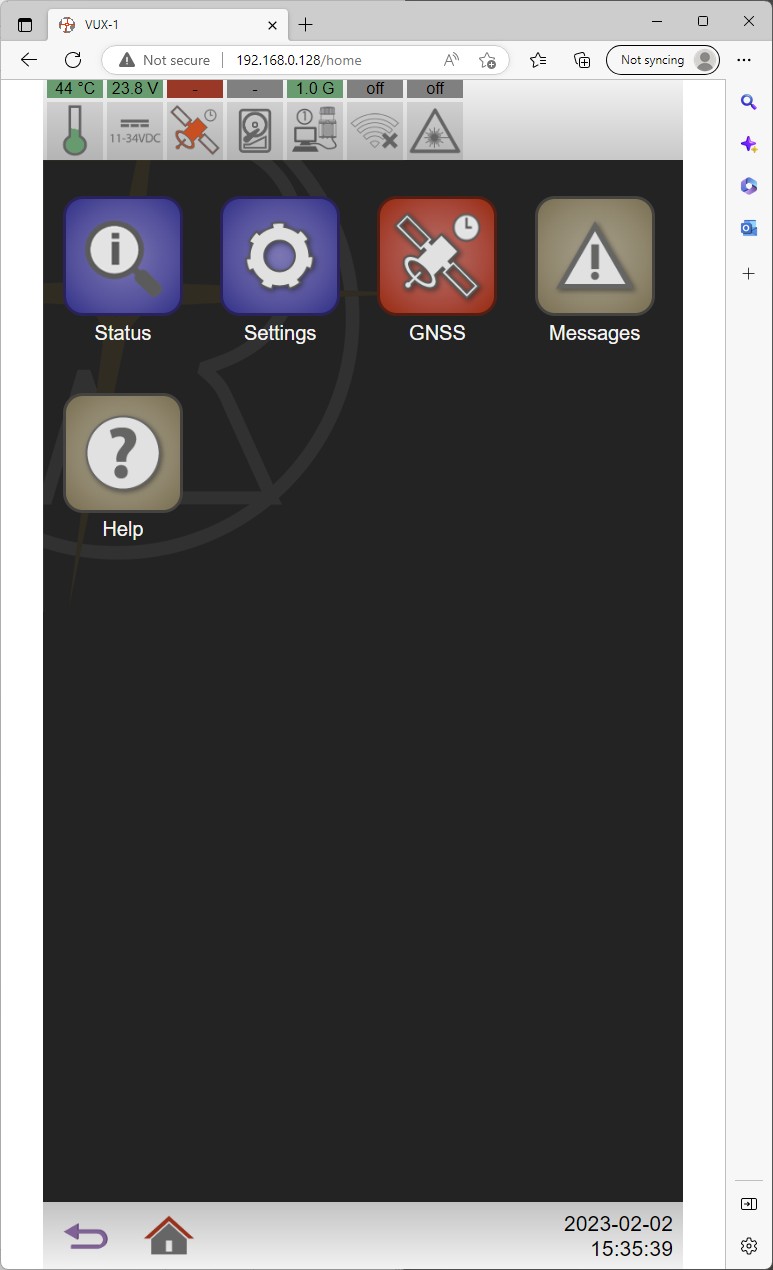
If you see this page it means there is
a) a successful network connection between Qinsy computer and laser scanner and
b) the IP address of the scanner is correct.
Note that this is the IP address that you must enter in the database template setup when defining the system properties. See paragraph Database Setup for all the details.
In order to verify whether the scanner is accepting the time message and pulse (PPS) from an external GNSS receiver select button Status and then GNSS.
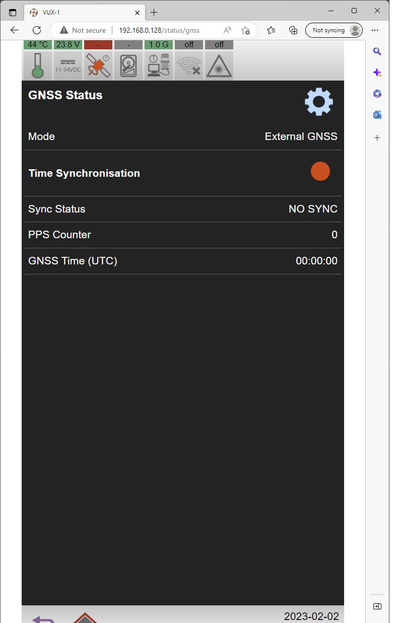
Example when time synchronization is not okay
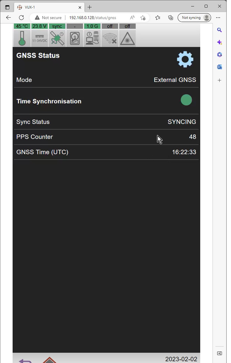
Example when timing is okay; the PPS Counter is incrementing every second, the GNSS Time is updating and the sync status is green.
When the scanner is interfaced to an external GNSS receiver but the time synchronization status is not okay you need to check the GNSS settings: select the shortcut Settings button in the upper right corner or go back to the Home page, select Settings, then GNSS:
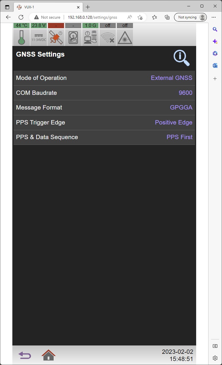
Make sure that
-
External GNSS is enabled
-
the baudrate of the time message is correct
-
the time message format
-
The correct PPS Edge and Sequence.
For these exact settings you may need to consult the GNSS receiver’s user manual.
When all settings are set return back to the GNSS Status page and verify that
-
Time synchronization is green.
-
Status is Synching
-
PPS Counter is incrementing every whole second
-
GNSS Time is correct updating
Remember these correct GNSS settings: you need to enter them also in the Controller Online setup.
Database Setup
Click here to expand setup details...
Internally a laser is treated as a multibeam system creating multibeam 'XYZ' observations.
Therefore add a Multibeam Echosounder system to your template setup and select driver "Laser Scanning - RIEGL miniVUX-HA (With UTC)”
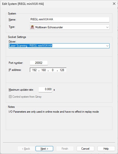
First Wizard Page
-
The Port number must be the same as the configuration port of the scanner, normally 20002.
The driver will communicate via this configuration port of the scanner.
The real-time line-stream is received via the data port and is always the configuration port number minus one: so normally 20001. Note that you don't have to enter this data port number in the setup.
-
It is important enter the IP address of the scanner, by default this will be something like 192.168.0.xxx.
-
The maximum update rate is not used, so leave it at zero.
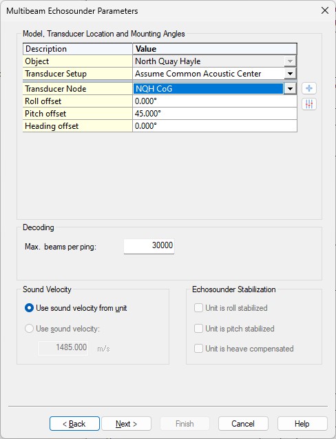
Second Wizard Page
-
Select the Transducer Node location that represents the data origin (0, 0, 0) of the laser scanner.
-
The mounting angle offsets (Roll, Pitch and Heading offset) should be established with a calibration procedure.
It is important to select the correct Scanner Mounting in the Qinsy Online setup: in that case you can leave the Roll, Pitch and Heading offsets close to zero so you don't have to use values anymore like +270 or -90, etc. -
Leave the Max. beams per ping value at 30000.
The actual number of beams will be variable and depends for example on the on-line used settings and on the targets being scanned.
Third Wizard Page
-
Just leave all values on this page at their defaults.
Fourth Wizard Page
-
Just leave all values on this last page at their defaults.
Online
Click here to expand online details...
Controller
When on-line, the laser unit can be controlled using the Controller.
Select Echosounder Settings, click on the Laser System icon, and select the 'Control' tab page.
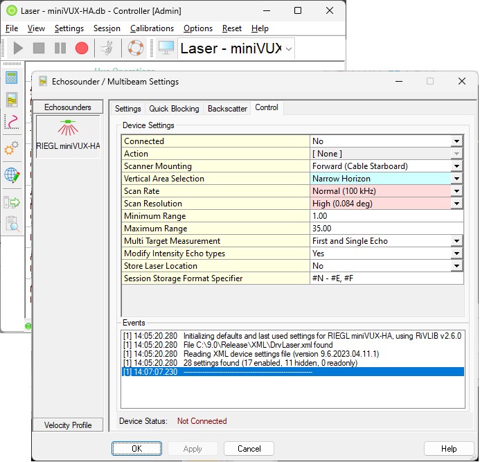
First of all: every-time when you come on-line a network connection has to be established between Qinsy and the laser unit. Set option 'Connected' to Yes and select the Apply button.
Please wait until you see in the Events list that a connection has been made successfully.
|
Connected |
Select Yes to connect (using TCP/IP) to the so-called LRC Server of the Laser Scanner. Under normal circumstances a successful connection will be established within a second. The driver will automatically disconnect when going offline, but you may also do this manually prior quitting. Notice the long timeout when no network connection can be made: it may take up to 20 seconds before you can continue. This may happen for example when the laser unit is still switched off or when the used IP address is not correct. After this timeout you will be informed in the Events list with a possible reason. So if it takes considerable more time, please check your network cable/setup/configuration. |
|
Action |
This is the only setting that does not require to press the Apply or OK button after a change: selected action will be sent immediately to the laser unit. Note that you must be connected first in order to select an action. Any selection will always revert back to [ None ] after each selected action. It is recommended to wait a few moments after each action, until the status in the Events list is updated with a message, because it takes some time for the unit to handle each command (action).
|
|
Scanner Mounting |
This is an important setting and it informs the driver how the scanner is physically mounted on the vehicle, with respect to its heading.
Further when the scanner is not horizontal but a bit tilted with an angle then you should enter this angle in the template database setup as mounting correction angle offset. |
|
Vertical Area Selection |
Scanner head rotates 360 degrees every line at high speed. Field of View: 0 degree means looking up, 180 degree means looking down, 90 degree looking left, 270 degree looking right. Very useful setting to exclude data which is not meaningful for your survey.
Note that the above labels do assume a normal horizontal mounted scanner. If your scanner is mounted with a large roll or pitch correction angle then expected results may be different. Excluded data d/t this setting will not be recorded |
|
Scan Rate |
Select the required scanner measurement rate, i.e number of points / sec.
Note that some combinations with Scan Resolution may not be possible but if that’s the case you will be informed in the events list. |
|
Scan Resolution |
Select the required vertical angle resolution.
The resulting speed of the scans (scans / sec) depends on a combination of the scan rate and the scan resolution. Use the following table to see what the results will be for all the possible Scan Rate / Scan Resolution combinations: 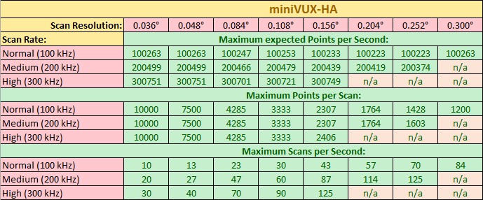
Note that some combinations with Scan Rate may not be possible but if that’s the case you will be informed in the events list. |
|
Minimum Range |
Set the minimum required range in meters. Valid Values: 1 to 270 meters. Using this setting is recommended, but be careful: Blocked data due to this setting (i.e. all pixels less than this range) will not be recorded! |
|
Maximum Range |
Set the maximum allowed range in meters. Valid Values: 1 to 270 meters. Using this setting is recommended, but be careful: Blocked data due to this setting (i.e. all pixels more than this range) will not be recorded! |
|
Multi Target Measurement |
One emitted laser pulse may hit one or several targets, causing one or several echo pulses.
Select here the type of echo pulse you want to decode. Notice that blocked data due to this setting will not be recorded. |
|
Modify Intensity Echo types |
When enabled, the original reported intensity and quality value for interior and last echo types will be modified. Note that the value for first and single echo types are never modified. |
|
Store Laser Location |
If enabled, an additional pixel with a zero co-ordinate (relative) will be added to each line scan, in order to indicate the exact laser scanner location in the resulting point cloud. This extra pixel will always have beam number 1 and its intensity/quality value will be zero. |
|
Use PPS |
Note that this setting is only available when laser driver '...(With UTC)' has been selected in your template setup. When enabled, the scanner needs a valid NMEA message and PPS pulse from an external GNSS receiver. The exact I/O parameters from this external GNSS need to be defined using the following settings below. |
|
PPS Trigger Edge |
Select the used trigger edge of the external GNSS PPS pulse.
It depends on the external GNSS receiver being used and you should therefore consult the receiver manual. This setting is only available when using Time Synchronization from an External GPS. |
|
GPS Baudrate |
Select the baud rate of the external GNSS receiver connected to the scanner This setting is only available when using Time Synchronization from an External GPS. |
|
GPS Format |
Select the format of the external Time message that goes to the scanner: This setting is only available when using Time Synchronization from an External GPS.
|
|
PPS Pulse/Data Sequence |
Select if the external Time Synchronization pulse comes before the GPS data string, or vice versa.
This setting is only available when using Time Synchronization from an External GNSS. |
|
Session Storage Format Specifier |
This format specifier can be used in combination with the Controller Session Storage Format Specifier #E. The following specifiers are supported (plus your own free text): #N: Name of the system (as defined in the template database setup)
The format specifiers are case-sensitive. If you use lower-case then only a value or index number will be displayed. So if you use #E in the Session Storage Setup the filename of the new recorded databases will automatically contain the scanner settings that you were using. |
|
|
|
Displays
Click here for useful display examples...
Generic Display
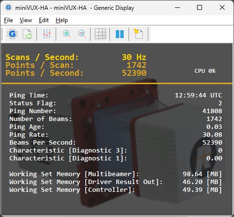
Use this display to check two important values:
-
Ping Age
The ping age value (in seconds) must be close to zero. -
Status Flag
Make sure that the status flag value is 2, meaning 'PPS OKAY'.
If the status flag is 0 then this either means that:-
you are using driver "Laser Scanning - RIEGL miniVUX-HA" so without "(With UTC)" in the driver’s name
-
or your template setup has no Time Synchronization system (aka PPS) defined
-
or your Qinsy Time Synchronization system is not working (please check)
-
or the miniVUX-HA Time Synchronization status is not 'Sync' (check WebGUI GNSS Status page)
-
Raw Multibeam Display
Use this display to visualize the raw incoming laser data.
The displayed data is still uncorrected for motion but it will give you a good indication whether laser data is decoded and what kind of targets are hit.
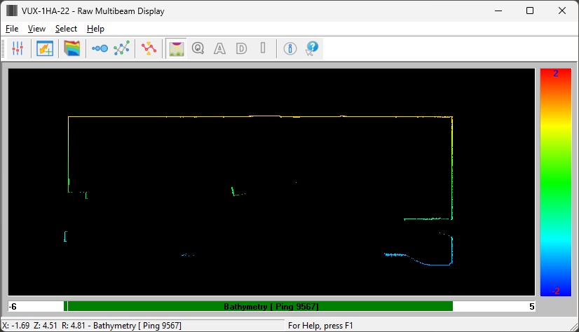
If you set Color Coding to Backscatter then the intensity (reported reflection) will be used for color coding.
Adjust the Backscatter Intensity scale, so set the minimum and maximum values to something like -40 to +40.
Bear in mind that all 3D laser data is presented in a 2D way.
Swath System Display
Use this display to visualize the calculated DTM results: final geo-referenced laser points fully corrected for motion and timing.
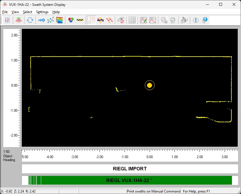
Bear in mind that all 3D laser data is presented in a 2D way.
3D Point Cloud Display
Use this display to visualize the calculated DTM results in a 3D environment.
DTM results are the final geo-referenced laser points fully corrected for motion and timing.
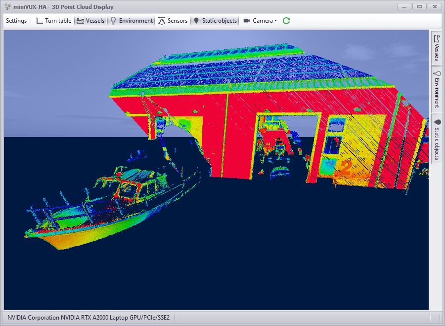
Sensors settings
-
For point color coding select your Color scheme attribute: for example color coding on Depth (=-Height) or on Intensity (as in the example above).
-
Also use the Sensor settings to show or hide the ping fan.
-
It is highly recommend to use a small Time window (e.g. 10 - 20 seconds) for keeping all data points in the view.
Use this display only if your computer has a high-end spec video card.
When you experience online performance problems it is advisable not to use this display at all, especially when recording laser data.
During replay and offline processing there shouldn't be any restrictions for using this display.
Additional Information
Click here for trouble shooting options...
If you experience problems using your laser scanner in combination with this driver or if you need additional information or support then please attach the daily laser log-file when submitting your JIRA support ticket.
At the bottom of this section you'll find the information on where to find this daily laser log file
Network Problems
Windows Firewall
A commonly reported problem is that network data is blocked by the Windows Firewall.
When this happens you may see that data does come in using other utilities (like the I/O Tester or the manufacturer's own software), but that the Qinsy driver does not accept any data.
The following (Windows 10) steps may solve this:
-
Go offline, open the PC Settings (Start menu, Settings)
-
Select Windows Firewall (Privacy & security, Windows Security, Firewall & network protection)
-
Select Advanced settings
-
Select Inbound Rules, highlight all 'Driver for Laser Scanning' entries and delete them using the right mouse popup menu (or Del key)
-
If you now go online, the Windows Security Alert message will pop up: now it is important to Allow access!
Multiple Network Cards
Another possible problem could be that your computer has more than one network card installed (e.g. LAN and WIFI) but within the same sub-net mask range (255.255.255.0).
It is recommended to make the first three digits unique for each network card IP address.
You may check the daily laser log-file; it will show the IP addresses for all available network adapters and indicates which one the driver will try to use automatically:
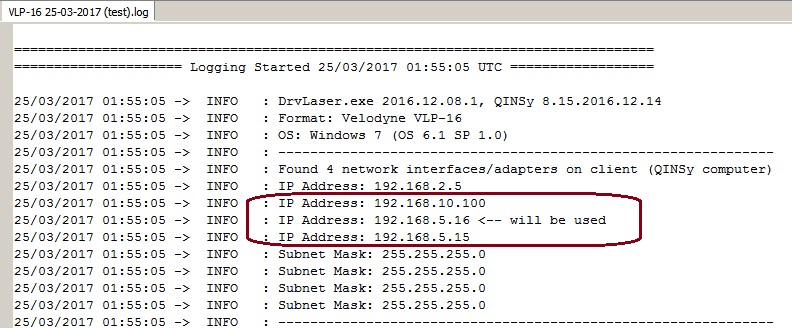
Please check that the driver is using the correct one!
Missing Data
If you occasionally experience gaps in your data, this may be caused by a general Windows setting that affects the data throughput of your network card.
Change the following registry key: HKEY_LOCAL_MACHINE\SOFTWARE\Microsoft\Windows NT\CurrentVersion\Multimedia\SystemProfile\NetworkThrottlingIndex
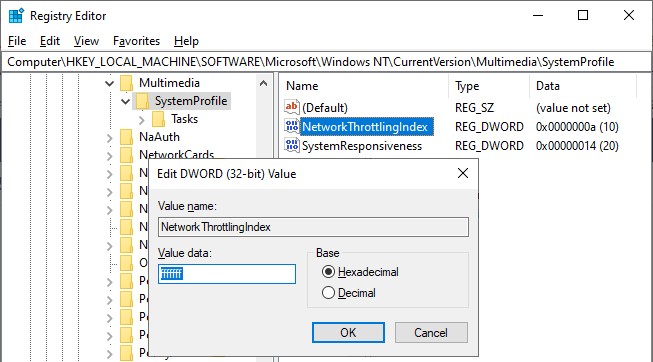
Set the new value to ffffffff (which will tell Windows to disable network throttling) and restart the computer.
Note that disabling network throttling may affect playing multimedia on your computer, but for laser scanning operations it is advisable to have a maximum data throughput of your network.
Daily Laser Log File
All user actions, system information and reported errors are logged in a daily laser log file which can be found in the current project's LogFiles subfolder.
The filename convention for this ASCII log-file is <System Name> DD-MM-YYYY.log, so every day there will be a new one.
Note that all time stamps in this log file are by default in UTC. An advanced user may change this to local time zone (LTZ) by changing the registry key:
HKEY_CURRENT_USER\Software\QPS\QINSy\8.0\Drivers\DrvLaser\Settings\TimeLogFileUtc value from 1 to 0.
Click here to improve your performance...
Improve Performance
Due to the enormous amount of data to be expected while scanning and recording, it is recommended to keep the system overhead as low as possible.
Here you'll find some tips and tricks in order to fine-tune your setup.
However, these are not strict rules, because each project is different and depends on the current situation and hardware being used. Your goal should be to keep your system CPU usage as low as possible.
HARDWARE
Storage
Make use of Solid State Drive (SSD), or fast SATA hard drive (7200 - 10000 rpm).
Network
Your network card speed should never be lower than the scanner's network speed. Use a network card that can be configured for 100Mbit or 1Gbit speed. Do not use USB Networking Adapters, because this may result in loss of data when huge amounts of data are being broadcast.
Virus Scanner
Disable Virus Scanner or at least the setting 'Scan Files when Writing/Reading to/from disk'.
Task Manager CPU
General Task Manager CPU Usage should be less than 50%. CPU load of each display must be less than 10-15%.
Make sure that the 'Working Set (Memory)' column for process Multibeamer.exe and/or DrvResultOut.exe is not constantly increasing, especially during recording. For detailed information about this see the section Real-time Performance Monitoring below.
PROJECT PREPARATION
Controller Laser Device Settings
During project preparation, establish the optimum settings in order to achieve the required results.
The most benefit you will gain from setting the Min/Max Range limits, Scan Speed, Scan Rate, Scan Resolution, Angle Resolution, Vertical Area Selection, Scan Area Selection and Sector Reduction as well as possible.
Especially the Vertical or Scan Area Selection is very important. Make use of Mask schemes to define areas which you don't want to scan.
ONLINE
Raw Multibeam Display
Open only one Raw Multibeam Display and more important: do not use the options 'Show Big Dots' or 'Draw Lines'.
Navigation Display
Open only one Navigation Display.
Preferably disable DXF and TIFF layers or other big background files. Note that these layers should only be used during project preparation.
When 'object tracking' is enabled, do not zoom in too close. Keep in mind that the display should not be 'refreshed' more than 1x per second.
3D Point Cloud Display
It is not recommended to use a 3D Point Cloud Display, unless your hardware contains a high-spec video card.
Under Sensor settings set the Time window setting to a short period, e.g. 10 sec
Static Grid / Dynamic Grid
Storage to a grid is not recommended and should be purely for display purposes: e.g. for checking the scan coverage or for showing the 95% Confidence Level statistics.
If you do want to see the scan coverage then it is advisable to store to a sounding grid and not to the dynamic surface
Do not use a small cell-size; preferably not less than 1.0 meter.
If you notice in the Navigation Display that the real-time sounding grid is updated with a delay then please increase the cell-size or disable the storage completely.
Note that in Replay (offline) there are no limitations and you may use small cell-sizes, e.g. 0.10 meter.
OFFLINE
Replay
In Replay there are no limitations as mentioned above: use as many displays as you like, store to sounding grids with small cell-sizes, update the dynamic surface, etc.
All this may only affect the replay speed, but the data integrity of your final DTM processing files should be fine.
COMPUTATION SETUP
While working online, disabling the laser system in your Computation Setup will have the most effect on the performance
The final footprints will not be geo-referenced, nor corrected for motion, heading or timing in real-time, which will save a tremendous amount of CPU power and memory usage.
This tip allows you to get the most out of your scanner: maximum scanning speed and maximum scanning rate, without the risk of losing scans due to performance issues.
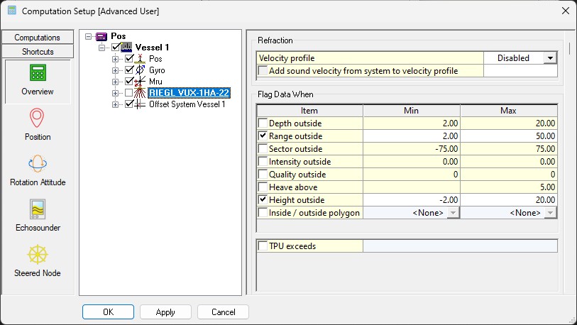
Drawback is that no DTM file (e.g. QPD) is created, nor a grid is filled, while working online.
In order to create a final DTM and/or Grid file you just need to Replay the recorded databases afterwards or load the recorded databases straight into Qimera for further processing.