
Description
This driver replaces SIS as the controlling software of the Kongsberg EM3002, EM2040 and EM2040C (Compact) multibeam systems in combination with Qinsy software.
The driver can be used to start / stop pinging, to monitor the clock synchronization, to set up operational parameters of the EM3002/EM2040(C) and to execute the internal BIST Tests of the EM3002/EM2040(C).
The topside 19 inch console is better known as the PU (Processing Unit). The term PU is used frequently throughout this document.
|
System |
Driver type |
|---|---|
|
EM 3002 |
|
|
EM 2040 |
|
|
EM 2040-C |
|
|
EM 2040-P |
|
Driver Information
|
Driver |
Kongsberg EM2040 Controller Kongsberg EM3002 Controller |
Interface Type |
Serial |
Driver Class Type |
Terminated |
|---|---|---|---|---|---|
|
No |
Input / Output |
Input and output |
Executable |
DrvKongsbergEMCtrl.exe |
|
|
Related Systems |
|
||||
|
Related Pages |
|
||||
Interfacing Notes
This chapter describes the interfacing to and from the EM3002/EM2040(C). The EM3002/EM2040(C) needs attitude data from a motion sensor for its beam steering.
Furthermore it requires an NMEA ZDA serial input and a 1PPS Time Synchronization signal. Optionally it can also use an NMEA GGA serial message for automatic ping rate reduction.
The PU outputs its data on a network connection to/from the Qinsy computer.
The EM2040(C) can optionally use Chirp (FM) transmit pulses and in that case requires interfacing of an Attitude Velocity sensor message.
Time Synchronization (previously PPS) and Time message
The EM3002/EM2040(C) requires input of a Time Synchronization signal and a ZDA time message at all times in order to synchronize its clock to the UTC clock.
Time Synchronization
Interface on PU: Time Synchronization cable from GPS to "1PPS" connector at the back of the PU.
The default active edge of the PPS signal is the falling edge, as of March 2013 this is selectable in the driver's Options dialog.
So make sure you know the PPS flank setting that the PU uses and set this correctly.
Time message
Interface on PU: Com1(default) or Com3 or Com4.
Format: NMEA ZDA
The baud rate is selectable 1200/2400/4800/9600/19K2/38K4/57K6/115K2 (see Options).
Other communication parameters must be Parity: None, Databits: 8, Stopbits: 1.
Motion
The EM3002/EM2040(C) requires input from an external motion at all times (@100Hz).
Interface on PU: Com2 (default) or Com3.
Format: Kongsberg Simrad EMxxxx binary format.
The baud rate is selectable: 1200/2400/4800/9600/19K2/38K4/57K6/115K2 (See Options).
Other communication parameters must be Parity: None, Databits: 8, Stopbits: 1.
The motion port can not contain and handle data from other systems (ZDA, Position).
Position
The EM3002/EM2040(C) can adjust its ping rates based on the vessel speed when set up correctly. In order to use this function it is necessary to feed an NMEA GGA Message into the PU on the same port as the Time Message.
Note that in the Option Dialog the GGA Usage should also be set to On.
Attitude Velocity
When the EM2040(C) is operated in 100m+ water depths it may be useful to use chirp TX pulses. In order to compensate for Doppler shifts the PU should be fed with an Attitude Velocity datagram from the motion sensor (via a network port).
The settings should be entered in the Options dialog of the driver (see below).
Control and Data output
The EM3002/EM2040(C) is controlled via the network by the EM Controller driver. The commands are issued over the network.
Preferably the EM3002/EM2040(C) is connected directly to the Qinsy PC via a network cross cable and NOT via a hub or switch.
Make sure The TCP/IP Settings of the:
-
Qinsy PC network card is set to:
-
-
IP 157.237.2.1 (last number may vary),
-
mask 255.255.0.0.
-
-
-
Kongsberg PU is usually set to
-
EM3002 -
-
IP: 157.237.2.61
-
-
EM2040(C)
-
IP: 157.237.20.40
No further programs like Kongsberg's Datadistrib are required.
-
-
Real Time - Sound Velocity Sensor
If your multibeam system utilizes a real time sound velocity sensor to correct the multibeam data then it should be interfaced straight into Qinsy because the sensor can not be interfaced to the PU directly.
Add New System of type "Underwater Sensor".
Add observation type "Sound Velocity' and set correct units, C-O's etc.
Data Ports
The data ports on which the PU sends out its bathymetry packets to Qinsy are by default set to 2001, 2002, 2003.
Any Qinsy driver that decodes bathymetry or sidescan data may use these port numbers.
The EM Controller driver uses port 2000 by default to communicate with the PU. Note that all mentioned port numbers are user definable.
Reserved port number are 2012, 2022, 2032, 2042, 1999. Please do not use these since they are used by the PU.
Database Setup
Make sure to use a Time Synchronization system in your setup otherwise the resulting bathymetry will contain artifacts caused by the PC clock not running synchronized.
Add New System of type "Miscellaneous". Select one of the "Kongsberg EM Multibeam Controller" variants depending on the system you are using. (See table above for details on the driver to select.)
Press the Finish button. No further settings are necessary; all other options are set online in the driver.
The multibeam system should be interfaced separately to Qinsy using the appropriate Multibeam driver.
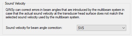
Now don't forget to assign the sound velocity probe to the multibeam system(s). This is required for the refraction correction.
In Database Setup change the parameters of the multibeam system by going through the system's setup wizard.
The last page of the wizard contains a selection for the sound velocity correction:
Real Time - Sound Velocity Sensor
If your multibeam system utilizes a real time sound velocity sensor to correct the multibeam data then it should be interfaced straight into Qinsy because the sensor can not be interfaced to the PU directly.
Add New System of type "Underwater Sensor".
Add observation type "Sound Velocity' and set correct units, C-O's etc.
Select your probe's observation here; make sure to do this for both heads if a dual head system is used.
Note: Since July 2011 it is possible to let this control driver send the sound velocity observation to the PU directly. In that case the beam angle corrections which are applied will be very small.
Online
The driver's main dialog looks as follows:
|
EM 3002D |
EM 2040C Dual |
|---|---|
|
|
For the EM system to work properly you should set up the driver options.
When online first make sure the EM controller driver is visible. Press the "Options" button in the driver. See Tab below:
This is divided into the following parts:
-
PU Setup
-
Program Options
-
Installation Parameters
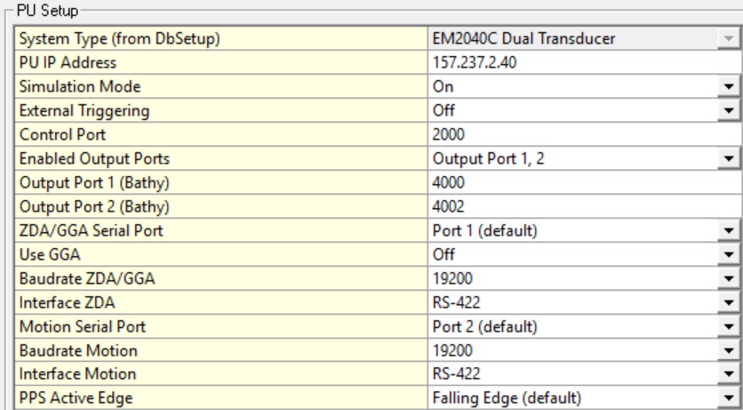
PU Setup
|
PU Setup |
Info |
||||||||||||||||||||||||||||
|---|---|---|---|---|---|---|---|---|---|---|---|---|---|---|---|---|---|---|---|---|---|---|---|---|---|---|---|---|---|
|
System Type |
Shows the kind of multibeam system; currently supports EM3002, EM3002D, EM2040, EM2040D, EM2040C, EM2040C Dual. If the system type is not correct then go offline, start Database Setup and change the driver type. |
||||||||||||||||||||||||||||
|
PU IP Address |
This is the IP address of the topside EM3002 Processor Unit (PU). The default value is 157.237.2.61 for EM3002 and 157.237.20.40 for EM2040(C) but this may be different for you unit. If the IP number is incorrect then the driver will not have a connection with the PU.
|
||||||||||||||||||||||||||||
|
Simulation Mode |
Set to 'On' if you want to run the PU in simulation mode. Normally this is set to 'Off'. |
||||||||||||||||||||||||||||
|
Control port |
This port number is used by the PU driver to send information to the Controller driver over the Network. This may be changed to any free port number. Default value is 2000. |
||||||||||||||||||||||||||||
|
Enable Output Ports |
These UDP port numbers are used by the PU to send data to the Qinsy drivers, default values: 2001, 2002, 2003. For example use multibeam driver for the port head to decode on port 2001, the multibeam driver for the starboard head on 2002 and the sidescan data on 2003. Use as few UDP ports as you can to transfer the required data to minimize the network traffic. Note on UDP output For the EM2040 and EM2040C (single and dual head) a single UDP output port should be used to transfer the data. This is to limit the number of Water column data packets.
We have also seen that Imagery data (Y) was not decoded. So if you run into one of these issues (or maybe something similar), please try the following setting: |
||||||||||||||||||||||||||||
|
ZDA/GGA Serial Port |
Select on which physical port the ZDA/GGA is interfaced to the PU. Select port 1 (default) or port 3 or 4. Preferably use port 1; if it is not available use one of the others. |
||||||||||||||||||||||||||||
|
Use GGA |
In order to use some of the advanced pinging options make sure to interface a GGA string to the Time port as well and enable this option. |
||||||||||||||||||||||||||||
|
Baudrate ZDA/GGA |
Select baud rate of ZDA/GGA message that is going into the PU. Other comm. parameters are: N,8,1. |
||||||||||||||||||||||||||||
|
Interface ZDA/GGA |
You can either select RS232 or RS422. Select the one that is defined by the output system. Known Bug If you interface an RS232 signal and select it in the Options menu, it does not work.
Affects versions: 8.18.1, 8.18.2 and 8.18.3
|
||||||||||||||||||||||||||||
|
Motion Serial Port |
Select on which physical port the Motion is interfaced to the PU. Select port 2 (default) or port 3. Motion should be exclusively on one port so do not share it with ZDA. Preferably use port 2; if it is not available you can try port 3. |
||||||||||||||||||||||||||||
|
Baudrate Motion |
Select baud rate of Motion message that is going into the PU. Other comm. parameters are: N,8,1. |
||||||||||||||||||||||||||||
|
Interface Motion |
You can either select RS232 or RS422. Select the one that is defined by the output system. Known Bug If you interface an RS232 signal and select it in the Options menu, it does not work.
Affects versions: 8.18.1, 8.18.2 and 8.18.3
|
||||||||||||||||||||||||||||
|
PPS Active Edge |
Select the flank of the Time Synchronization TTL pulse on which the exact second turnover is valid, select either Falling Edge (Kongsberg Default) or Rising Edge. |
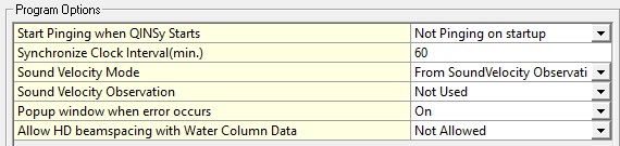
Program options
|
Program Options |
Info |
|---|---|
|
Start Pinging when Qinsy Starts |
Depending on this option the driver can order the PU to start pinging immediately on start-up of the Controller or not. For user convenience it may be handy to start pinging automatically.
|
|
Synchronize Clock Interval(min.) |
Time in minutes how often the driver orders the PU to carry out a clock synchronization procedure, default is 60 minutes. The driver will never carry out the synchronization procedure when Qinsy is logging as it may affect the operation of the sounder shortly, so the procedure will be carried out when the interval expires and the user stops the recording. |
|
Sound velocity Mode |
|
|
Sound Velocity Observation |
Select the sound velocity observation here (only in combination with mode "From Sound Velocity Observation"). |
|
Popup window when error occurs |
If this option is activated then the driver dialog pops up when it is minimized and an error occurs (by default on). For debugging purposes it can be switched off. |
|
Allow HD beamspacing with Water Column Data |
Only relevant if the watercolumn option is enabled in Database Setup for the multibeam driver. For water column processing in the Qinsy Watercolumn Inspector High Density beam spacing should not be used as the raw beam data can not be related anymore to the watercolumn data. If this options is set to "Allowed" then the high density mode can still be used (e.g. if you are only interested in viewing the watercolumn data in the Raw Multibeam Display). |
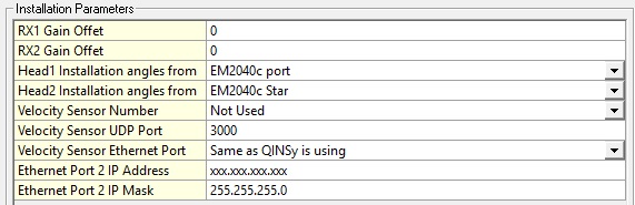
Installation parameters
|
Installation Parameters |
Info |
|---|---|
|
RX1 Gain Offset |
Gain offset of Transducer Head 1 (-10 to +10 dB, default 0 Db). Refer to Kongsberg documentation for more information. |
|
RX2 Gain Offset |
Gain offset of Transducer Head 2 (-10 to +10 dB, default 0 Db). Refer to Kongsberg documentation for more information. |
|
Head1 Installation angles from |
Select the Port multibeam system here as defined in the Qinsy template. This is VERY IMPORTANT because the installation angles (pitch/roll/heading offset of the transducer) are needed by the PU and derived from the selected system. Make sure that the installation angles that are entered in Database Setup are at least approximately correct. EM2040(C) Only: Make sure the heading offset is correct, either around 0 (normal) or around 180 (reversed). For the TX transducer the heading offset should be approximately 0 degrees when the connector points to port side or 180 degrees when the connector points to starboard. For the RX transducer the heading offset should be approximately 0 degrees when the connector points to the bow or 180 degrees when the connector points to stern. |
|
Head2 Installation angles from |
Same as for Head1 but now for the starboard transducer. Leave to "Not Used" for a single head system. Note Failure to select the correct Multibeam System(s) here will result in wrong bottom detection on the echosounder for dual head systems. |
|
Velocity Sensor Number |
In case FM chirp pulses are used a motion sensor will need to supply Attitude Velocity data over the network to the PU for the Doppler correction. Select here either None if not used, or Motion 1 or Motion 2. Refer to Kongsberg documentation for more info. |
|
Velocity Sensor UDP Port |
Port number of which velocity attitude data is received on the PU. |
|
Velocity Sensor Ethernet Port |
Which physical Ethernet connector is used to receive velocity attitude data can be selected here. Newer PU models may have two network connectors. Select "Same as Qinsy is using" or "Ethernet Port2". |
|
Ethernet Port 2 IP Address |
IP Address of the PU's second Ethernet port. |
|
Ethernet Port 2 IP Mask |
IP Mask of the PU's second Ethernet port. |
Settings file
When the Qinsy Controller closes then all the selected options are stored in an *.xml file (Ks_EmCtrl_Options.xml), located in the MSWindows user application data local folder.
When the Qinsy Controller is restarted then the settings will be restored from this *.xml file. If the *.xml file is not found then default options will be used.
Absorption
Absorption Table (EM2040(C)) : The driver sends a default absorption table to the PU. These are currently hard coded.
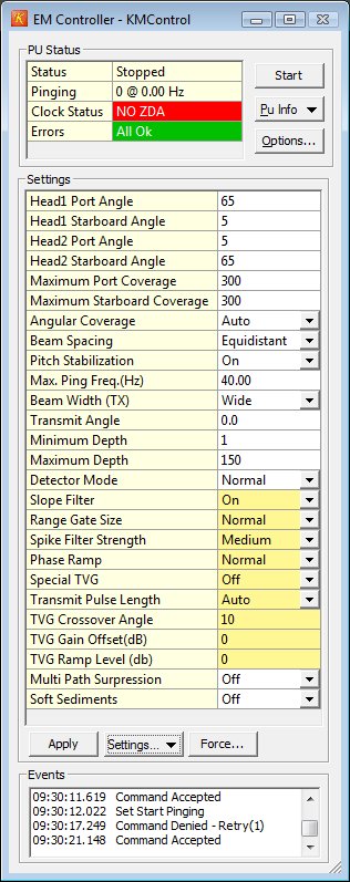
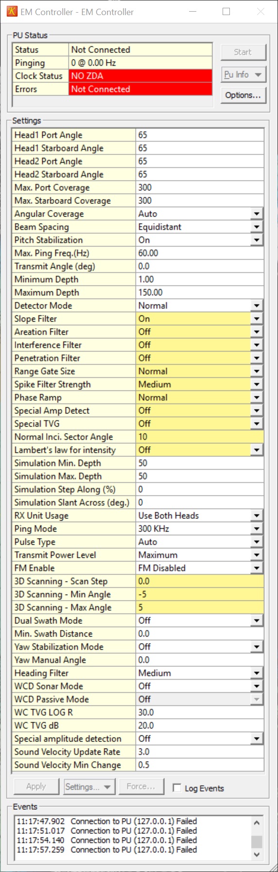
PU Status
The PU Status view is used to monitor the current state of the echosounder.
-
Status
Status field can either be "Stopped" when echosounder is not pinging, "Active" when pinging normally and "Simulator" when pinging in simulation mode.
-
Pinging
Shows last ping number and the ping frequency as reported by the echosounder.
Clock Status
Shows information about the echosounder clock and how well it is synchronized to the Qinsy clock.
The field can contain the following values:
|
Status |
Info |
|---|---|
|
Ok |
No errors occurred |
|
NO ZDA |
NMEA ZDA is not decoded properly or not interfaced correctly |
|
PPS PULSE ERROR |
Time Synchronization Signal (PPS) is not detected by the PU |
|
PPS TIME ERROR |
PU clock is deviating from the ZDA more than 750 msec |
|
CLOCK ERROR |
PU reports a clock failure in status message |
|
BAD SYNC |
PC clock deviating more than 50 msec from PU clock |
Errors
If an error is reported by the PU then it is shown here.
Current Kongsberg Multibeam settings are displayed here. If one or more settings are changed, user should press the "Apply" button to actually send the settings to the PU. Only the changed settings are sent to the sounder. For more information on the meaning of the settings please refer to the Kongsberg SIS manual.
Echosounder settings are stored in an *.xml file. The current settings can be saved to an *.xml file with a user defined name. These settings can also be restored. This can be useful if you repeatedly survey in different areas that require different settings. When the Set Default option is chosen then for every setting the default value is restored.
XML naming convention for saved settings files:
Ks_EmCtrl_User_AAA.xml AAA is the user defined name.
A help description is available in a tooltip when the mouse is placed over the setting label.
|
Setting |
Info |
|---|---|
|
Head1 Port Angle |
Port side maximum swath angle in degrees, angle are ref the vertical.
|
|
Head1 Starboard Angle |
On a single transducer system this is the starboard side maximum swath angle, angle in degrees, ref the vertical.
|
|
Head2 Port Angle |
Dual Head system, starboard transducer, port side maximum swath angle in degrees, angle are ref the vertical.
|
|
Head2 Starboard Angle |
Dual Head system, starboard transducer, starboard side maximum swath angle in degrees, angle are ref the vertical.
|
|
Max. Port Coverage |
This parameter allow you to define the maximum swath width to port side by selecting values in meters.
|
|
Max. Starboard Coverage |
This parameter allow you to define the maximum swath width to starboard side by selecting values in meters.
|
|
Angular Coverage |
Manual: If Angular Coverage is set to manual, the values defined as Max port and starboard angle above (in degrees) are used directly.
Auto: If Angular Coverage is set to Auto, the maximum coverage (in meters) and the maximum angles will set the swath width limit.
|
|
Beam Spacing |
Depending on the purpose of the survey, you may define the distribution of the beams on the seafloor. Equidistant: This setting gives a uniform distribution of soundings on the seafloor,
High density (Equidistant): In this mode the number of soundings are increased.
|
|
Pitch Stabilization |
At open sea, the swath area on the bottom will move back and forth following the vessel pitch.
|
|
Max. Ping Freq.(Hz) |
The ping rate is normally limited by the acquisition time (two way travel time) of the receive data plus a little overhead.
|
|
Transmit Angle (deg) |
This function can be used to tilt the transmit sector forward and backwards.
|
|
Minimum Depth |
These parameters define the operational depth range.
|
|
Maximum Depth |
These parameters define the operational depth range.
|
|
Detector Mode |
Select detector mode to optimize the systems ability to recognize the bottom, wreck, structures, etc., depending on water condition.
|
|
Slope Filter |
With this filter enabled, the system checks for bottom slopes that tilt inwards.
|
|
Aeration Filter |
If the transducer installation suffers from air bubbles close to the transducer, the system may have problems with bottom tracking.
|
|
Sector Tracking Filter (EM 2040 only) |
The transmitter operates with one, three or nine pulses within each ping.
|
|
Interference Filter |
If the vessel is equipped with other echo sounders on sonars operating on frequencies close to the echo sounder, you may experience interference.
|
|
Penetration Filter |
Penetration Filter |
|
Range Gate Size |
Choose between SMALL, NORMAL and LARGE.
|
|
Spike Filter Strength |
Choose between OFF, WEAK, MEDIUM and STRONG.
|
|
Phase Ramp |
Choose between SHORT, NORMAL and LONG.
When set to NORMAL, the number of samples used for phase detection will normally be equal to twice the range distance between the beam and it’s neighbours.
SHORT phase ramp gives the best resolution, but a side effect can be that the detected bottom will have increased noise.
|
|
Special Amp Detect |
Use for soft sediments |
|
Special TVG |
The EM 2040 does not use TVG, but in the bottom detection process a TVG function may be applied.
|
|
Transmit Pulse Length |
Set the Length of transmit pulse, it is advised to leave this on Auto |
|
Normal Inci. Sector Angle |
This value is used to define the angle (in degrees) at which the bottom backscatter can be assumed not to be affected by the strong increase at normal incidence.
|
|
Lambert's law for intensity |
Enable to have the unit use Lambert's law to calculate beam intensity. Together with the 'normal incidence sector angle' this will help to provide a more uniform beam intensity across the swath |
|
TVG Gain Offset(dB) (EM3002 only) |
Gain Offset, Default 0, min -8, max 8. |
|
TVG Ramp Level (db) (EM3002 only) |
Ramp Level, Default 0, min -8, max 8. |
|
Multi Path Suppression (EM3002 only) |
Multipath Suppression |
|
Absorption Coefficient (EM3002 only) |
The absorption coefficient depends upon depth, water temperature, salinity and frequency.
|
|
Simulation Min. Depth |
Minimum depth in simulation mode. |
|
Simulation Max. Depth |
Maximum depth in simulation mode. |
|
Simulation Step Along (%) |
|
|
Simulation Slant Across (deg.) |
|
|
RX Unit Usage |
Toggle individual transducers on or off |
|
Ping Mode |
This parameter defines the operational frequency of the multibeam echo sounder.
|
|
Pulse Type |
The pulse can be set to be of the following types:
|
|
Transmit Power Level |
TX power can be lowered 10 or 20 dB to avoid saturation in shallow water.
|
|
FM Enable |
This can be used to turn off the use of FM pulses.
|
|
Sector Mode (EM 2040 only) |
This parameter controls the use of transmit sectors.
|
|
3D Scanning - Scan Step |
Fore Aft Scanning - Step of Scanning in Degrees, OFF = 0 |
|
3D Scanning - Min Angle |
Fore Aft Scanning - Minimum Angle |
|
3D Scanning - Max Angle |
Fore Aft Scanning - Maximum Angle |
|
Dual Swath Mode |
Using dual swath implies that two fans are transmitted, one in front of the other.
OFF: Dual swath is disabled (i.e. standard single swath).
|
|
Min. Swath Distance |
Set minimum along distance in meter between swaths (in along ship direction).
|
|
Yaw Stabilization Mode |
Three stabilization modes are available:
REL. MEAN HEADING: This setting places the transmitter sector perpendicular to a filtered course corresponding to the vessel’s current mean heading.
|
|
Yaw Manual Angle |
Only used with manual Yaw Stabilization Mode, Allows you to enter the vessel’s heading manually. |
|
Heading Filter |
This parameter specifies the level of filtering of the heading.
|
|
WCD Sonar Mode |
When enabled, this shows a larger wedge of Water column Data.
|
|
WCD Passive Mode |
When enabled, no Tx pulses are emitted. This functionality can be used to identify sources of noise |
|
WC TVG LOG R |
Logarithmic parameter of the water column TVG function |
|
WC TVG dB |
Offset parameter of the water column TVG function |
|
Special amplitude detection |
Special amplitude detection |
|
Sound Velocity Update Rate |
This allows the user to change when a sound velocity update is sent.
|
|
Sound Velocity Min Change |
This allows the user to lower the threshold of when a sound velocity update is sent.
|
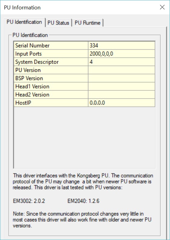
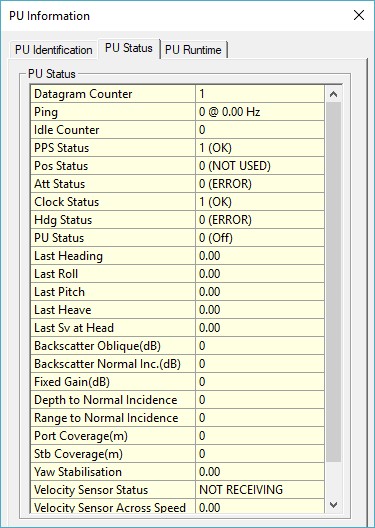
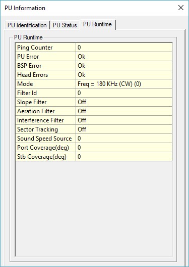
PU Information
This dialog shows the Identification information of the echosounder, the contents of the last status datagram and the contents of the last received runtime datagram.
Reviewing these pages may be useful to debug the echosounder or to retrieve information on the current software version running in the PU and head(s).
BIST Tests
The BIST Test dialog is used to command the PU to perform some internal tests inside the echosounder. To start a test press one of the test buttons.
The result of the test is stated behind the button.
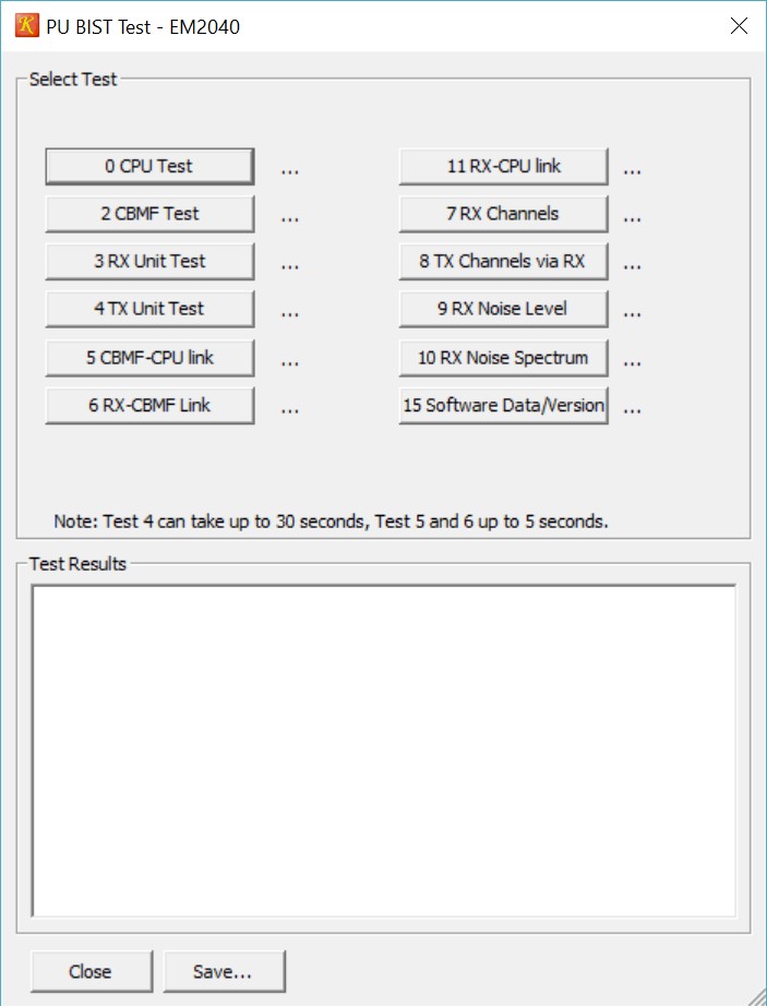
Results of the tests are shown in the lower part of the dialog and can be saved to a file.
Notes:
Some tests take a while to execute especially if errors are detected, e.g. the BSP test can take up to 30 seconds if errors occur.
Each test can be performed for both heads. So for a dual head system execute all tests for Head 1 and then all tests for Head 2.
Test 31 is not a real test but actually a command to update the HCT software, please contact Kongsberg for more details.
Initiating a BIST test stops the pinging of the sounder, so pinging should be restarted when BIST testing is finished.
This is a menu option that contains several options:
Swap port/starboard angles
This will swap over the port /starboard transducer opening angles (similar to SIS).
Show/Hide Settings...
Launches the dialog that allows you to customize which settings are presented to the user.
Save As...
Takes current settings and stores them into an *.xml.
Load Defaults...
Loads default settings into the settings grid.
Load..
Allows you to load a previously stored settings file.
This is the Kongsberg Force Depth option.
If the bottom tracking of the sounder is lost you can try to force it to the correct depth again.
Overview of events occurred in the connection to the PU.
Naming and storage location.
The following XML files are used by the driver:
Ks_EmCtrl_Options.xml Driver Options
Ks_EmCtrl_Settings.xml Last used settings
Ks_EmCtrl_User_*.xml User defined settings files
All xml files reside in a subfolder called DrvKongsbergEMCtrl of the local App data folder.
This folder can be found in the Tools menu in the Console using the option Explore Application data folder / local.
If user settings are saved then this file is also saved in this folder.
You'll need Skype CreditFree via Skype