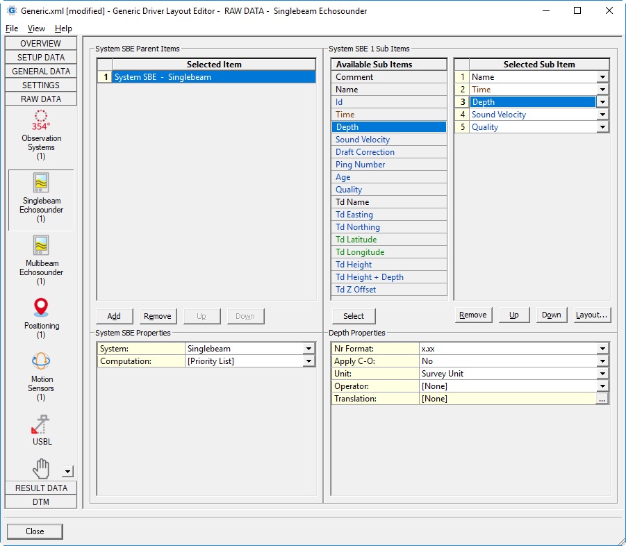
Singlebeam Echosounder

| Parent Item | |
|---|---|
| System: | List with all available singlebeam echosounder transducers that exist in the currently selected Qinsy database. (see General Layout Information about loading a Qinsy database). Note that a singlebeam echosounder system may have more than one transducer defined. |
| Computation: | This option to select a computation is only needed for transducer node sub items (e.g. Td Easting, Td Northing, Td Height + Depth, etc.)
|
| Skew: |
Notes:
Note that terminology 'Deskew' and 'Skew' means the same in Qinsy: they are not opposites of each other. |
| Sub Item | Description | Value Type | |||||||||||||||
|---|---|---|---|---|---|---|---|---|---|---|---|---|---|---|---|---|---|
| Comment | User-defined free text
| text | |||||||||||||||
| Name | Name of the Singlebeam Echosounder System (plus the Transducer label) as defined in Database Setup | text | |||||||||||||||
| Time | Time of the last raw update | time | |||||||||||||||
| Depth | Value depends on the Apply C-O property.
| double | |||||||||||||||
| Sound Velocity | The used sound velocity value as reported by the unit. In case the unit (message format) does not output the used sound velocity (see also Status Flag) then it will be the used sound velocity as entered in Database Setup.
| double | |||||||||||||||
| Velocity Mode | An integer value (code) representing the selected Sound velocity mode as defined in the Controller Echosounder Refraction setting. By default a translation table is added to convert the code into readable text:
Feel free to modify or remove the translation table. | int | |||||||||||||||
| Draft | Decoded transducer draft value from the unit (see also Status Flag) or the manual draft value as entered in the Controller Echosounder Refraction setting. Note that the draft here is the distance between waterline and transducer and should not be confused with the vessel's draft as defined in the Computation Setup, Object Height. | double | |||||||||||||||
| Heave | Decoded heave value from the unit. Value will be empty when the unit does not output a heave (see also Status Flag). | double | |||||||||||||||
| Index | Decoded index offset value from the unit. Value will be empty when the unit does not output an index offset (see also Status Flag). Index (or index offset, is also known as constant k, initial delay or electronic delay) is a fixed offset which depends on the transducer hardware being used and should be determined by a calibration procedure. | double | |||||||||||||||
| Status Flag | This integer value represents a bit-wise flag where each bit indicates if the sound velocity, the draft, heave and/or the index offset is part of the output message from the unit.
For example when the status flag value is 3 it means that the echosounder unit is outputting the used sound velocity and draft. If the status flag value is zero then none of these additional values are known by the driver. | int | |||||||||||||||
| Ping Number | Normally an increasing number. This value is decoded from the header data, coming from the echosounder system itself. | int | |||||||||||||||
| Age | The difference between the triggering time and the time of the last raw update. Normally a positive value in seconds.
| double | |||||||||||||||
| Quality | Same quality as seen in Observation Physics Display. | double | |||||||||||||||
| Td Name | The name of the node, as defined in Database Setup. This node is selected as transducer in the echosounder system setup on the 2nd wizard page. | text | |||||||||||||||
Td Easting Td Northing | The easting and northing of the transducer node as calculated by the selected computation. Easting and Northing are always on Survey Datum (also known as Horizontal Datum) | double | |||||||||||||||
Td Latitude Td Longitude | The latitude and longitude of the transducer node as calculated by the selected computation. Latitude and Longitude are by default on Survey Datum (or Horizontal Datum), but the 2nd datum may also be selected if available in the Geodetic Configuration.
| geo | |||||||||||||||
Td Height | The height of the transducer node as calculated by the selected computation. Height is by default on Chart Datum (also known as Vertical Datum) but other datums can also be selected.
| double | |||||||||||||||
Td Height + Depth | A combination of the transducer height plus the corrected depth value. For this combination the height reference is always Chart datum and the depth value is already corrected for the sound velocity mode as defined in the Controller Echosounder Refraction setting. Note that this value is not as accurate as the final DTM Results (actual calculated footprint value using SVP ray tracing, etc.) but it gives a good indication of the current water depth. | double | |||||||||||||||
| Td Depth | The depth of the transducer node with respect to the actual water level. | double | |||||||||||||||
| Td Z Offset | The vertical offset of the transducer node from the object reference point as defined in the Database Setup. A negative value means that the transducer node is below the object reference point. | double | |||||||||||||||
