
Multibeam Echosounder
Parent Item | |
|---|---|
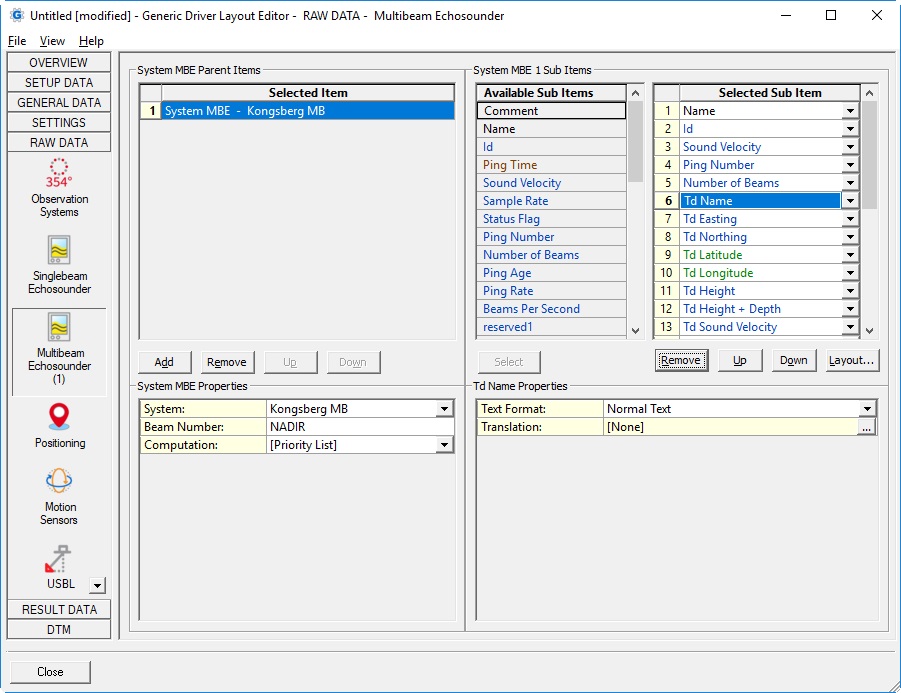
System: | List with all available multibeam and multi-transducer echosounder systems that exist in the current selected Qinsy database. |
Beam Number: |
|
| Computation: | This option to select a computation is only needed for transducer node sub items (e.g. Td Easting, Td Northing, Td Height + Depth, etc)
Note that when the layout is used for Export (offline), you can not select entry [Priority List], you must select a 'real' computation from the list. |
| Skew: |
Notes:
Note that terminology 'Deskew' and 'Skew' means the same in Qinsy: they are not opposites of each other. |
| Sub Item | Description | Value Type | |||
|---|---|---|---|---|---|
| Comment | User-defined free text
| text | |||
| Name | Name of the selected system, as defined in Database Setup | text | |||
| Ping Time | Time of the last transmitted ping (part of the message) | time | |||
| Sound Velocity | Sound velocity.
| double | |||
| Sample Rate | The number of samples per second (Hz). For multibeam systems: if this value is > 0 then it will be used to calculate the Beam Slant Range. For laser scanners: value will always be 1. | integer | |||
| Status Flag | Additional status information decoded from the header data. | integer | |||
Ping Number | Increasing number. | integer | |||
Number of Beams | The total number of beams. | integer | |||
Ping Age | The difference between the triggering time and the time of the last transmitted ping (see Ping Time above).
| double | |||
Ping Rate | Number of pings per second (Hz), as reported by the unit. Note that not all echosounders (or laser scanner units) do report this value, in that case you will see a value of zero. | double | |||
| Beams Per Second | The number of beams per second. Formula: Number of Beams * Ping Rate | integer | |||
| Characteristic | Some multibeam echosounders or laser scanners may report additional characteristic values. Use the Parameter property to select what characteristic value you want to monitor: Parameter
Note that when the selected characteristic is not supported by your system then the value will be empty. | double | |||
| Td Name | The name of the node, as defined in Database Setup. | text | |||
Td Easting Td Northing | The easting and northing of the transducer node, as calculated by the selected computation. Easting and northing are always on Survey Datum (also known as Horizontal Datum) Note that the Td position for multi-transducer systems depends on the selected beam number. | double | |||
Td Latitude Td Longitude | The latitude and longitude of the transducer node, as calculated by the selected computation.
Note that the Td position for multi-transducer systems depends on the selected beam number. | geo | |||
Td Height | The height of the transducer node, as calculated by the selected computation. Height is by default on Chart Datum, but Survey Datum, WGS84 (or ITRF2008), the Actual Water Level, the Mean Water Level, or the Geoid Model Level may be selected.
Note that the Td position for multi-transducer systems depends on the selected beam number. | double | |||
Td Height + Depth | A combination of the transducer height (on Chart Datum), and the raw depth value. For multibeam systems the 'depth' is calculated using the slant range and corrected for the beam angle, the current roll of the vessel and the mounting roll offset for the RX transducer, as defined in Db Setup. Note that this value is not as accurate as the final DTM Results (actual calculated footprint value) because SVP ray-tracing is not taken into account nor the mounting pitch offset as defined in Db Setup but it gives a good indication of the current depth.
| double | |||
| Td Sound Velocity | The value will be the interpolated/extrapolated sound velocity from the current sound velocity profile at the actual water level depth for the multibeam transducer node. | double | |||
| Td Depth | The depth of the transducer node with respect to the actual water level. Note that the Td position for multi-transducer systems depends on the selected beam number. | double | |||
| Td Z Offset | The vertical offset of the transducer node from the object reference point as defined in the Database Setup. A negative value means that the transducer node is below the object reference point. Note that the Td position for multi-transducer systems depends on the selected beam number. | double | |||
Beam Time | For most MBE system types this is the same as the Ping Time. | time | |||
Beam Number | Beam number. Lowest value is 1. | integer | |||
Beam Travel Time | (Item not applicable for MBE system type X/Y/Z). | double | |||
Beam Slant Range | The Beam Slant Range is calculated according the following formula, which depends on the MBE system type:
| double | |||
| Beam Tilt Angle | The beam tilt angle only accounts for MBE type Rho/Theta, and will be empty for other types of mbe systems. | double | |||
Beam dX | The value is the x-component for a MBE type X/Y/Z system, and will be empty for other types of mbe systems. | double | |||
| Beam dY | The value is the y-component for a MBE type X/Y/Z system, and will be empty for other mbe systems. | double | |||
| Beam dZ | The value is the z-component for a MBE type X/Y/Z system, and will be empty for other mbe systems. | double | |||
| Beam Angle | The beam angle in degrees as reported by the MBE unit, which is only applicable for MBE type Rho/Theta systems. Example Rho/Theta Type: In case your MBE is type X/Y/Z, the angle will be calculated using the reported Beam X, Y and Z value and depends on the selected Reference property. Value will be zero for MTX type systems.
| double | |||
| Beam Delay | Beam correction time in seconds. | double | |||
| Beam Quality | A value between 0 and 255. Please check the driver's documentation of your used multibeam or laser system what the decoded quality value represents | integer | |||
| Beam Intensity | An indicator for the beam intensity or reflectivity. Please check the driver's documentation of your used multibeam or laser system what the decoded intensity value represents | double | |||
Beam Tx Sector Nr | integer | ||||
| Beam Detection Nr | integer | ||||
| Beam Reserved | For most multibeam and laser systems this value will not be used and therefore zero. Some specific laser drivers will use this 'reserved' entry to store additional information for the decoded laser pulse. The value will always be between 0 and 255. When you are using a RIEGL laser this value will be the reported deviation; according their documentation a measure of pulse shape distortion. A larger value for deviation indicates larger distortion. When you are using a Teledyne Polaris laser this value will be the number of returns; indicating how many returns there are for the shot, which can be up to 4. When you are using a Velodyne or Ouster laser this value will be the fire index of the beam. | integer |