This document explains how to set up an Applanix POS MV with Qinsy 9.2.0.
It contains the following parts:
General
Warning
QPS suggests to always interface the POS MV directly to Qinsy like shown below.
There are solutions where you interface the POS MV to a sonar and then the sonar relays this information to Qinsy.
However, this could result in latency issues.
In case you have questions on this, please contact QPS Support.
Conventions
|
Positive |
POSMV |
Qinsy |
|---|---|---|
|
X |
Bow |
Starboard |
|
Y |
Starboard |
Bow |
|
Z |
Down |
Up |
Useful Links
-
Drivers Manual
-
Equipment Space (Under construction!)
POS MV - Setup
This part will explain what you will need to set up in POS VIEW. The offsets are just examples that are both used in Qinsy and POS VIEW.
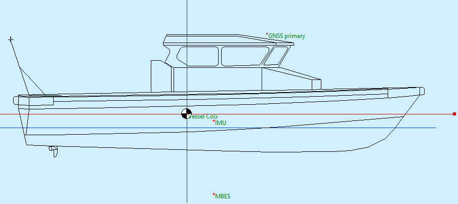
This is what it will look like in POS VIEW vs Qinsy:
|
POS VIEW |
Qinsy |
|---|---|
|
|
|
POS VIEW - Lever Arms and Mounting Angle
Ref. to IMU Target
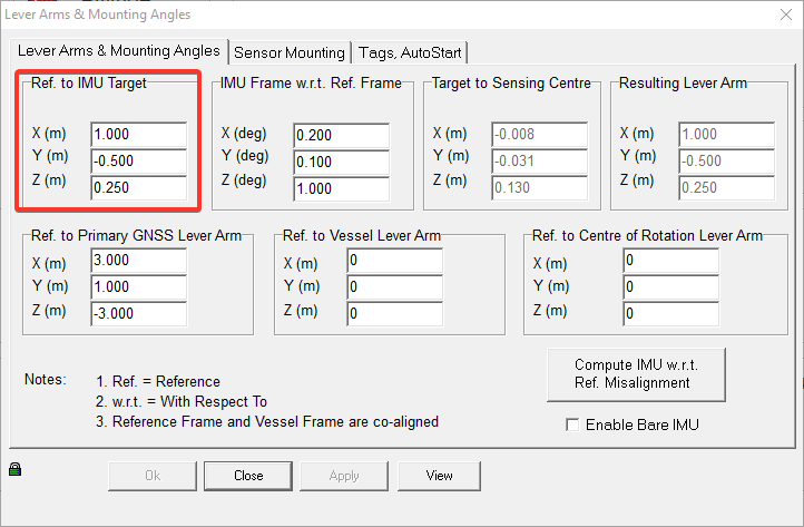
This should represent the offset between the Center of Gravity (CoG) and the IMU. So the Reference is the CoG.
For Qinsy, the CoG (or a point nearby) is defined as the reference point.
IMU Frame with reference to Ref. Frame
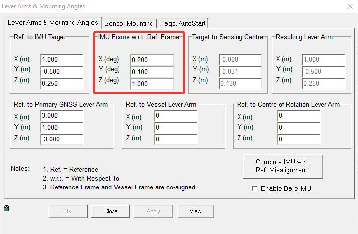
The is the orientation of the IMU relative to the vessel frame. This should be entered in POS VIEW and not in Qinsy.
This is because Qinsy cannot correct for cross-talk at the time of writing of this document.
Ref. to Primary GNSS Lever Arm
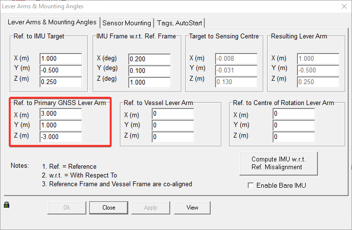
Enter the offset from the Reference point to your Primary GNSS.
POS VIEW - Sensor Mounting
Ref. to Sensor 1/2
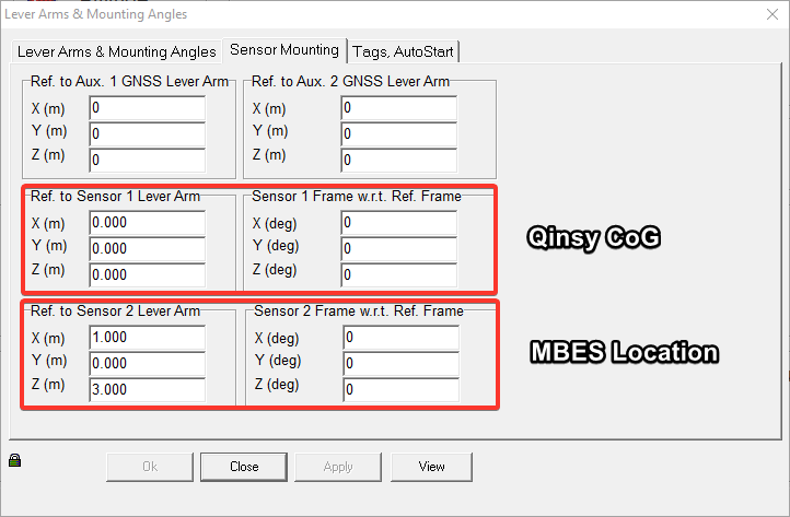
Sensor 1
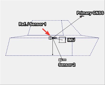
For the Qinsy setup it is preferred to leave this at zero. This means that the Reference and Sensor 1 location are the same.
This means that the Sensor 1 position is valid for the Qinsy CoG.
Sensor 2
You usually also need to output messages from the POS MV to the MBES. Sensor 2 can be used for this.
POS VIEW - Tags, AutoStart
Time Tag 1
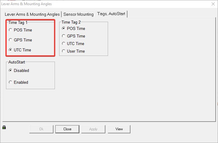
Select UTC Time for Time Tag 1.
POS VIEW - Ethernet Realtime
This part explains which message groups need to be sent to Qinsy.
There is also the option to log data. For more info and how to work with POS PAC, please ask Applanix.
This can be used to post process your data to create an improved track. This improved track can then be imported to Qimera.
Groups
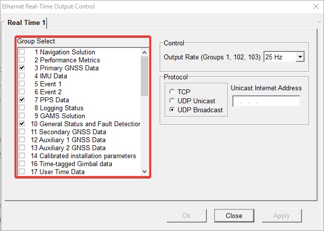
For a standard POS MV - Qinsy setup you will need to enable the following messages:
|
Message groups |
|
|---|---|
|
3 |
Primary GPS Data |
|
7 |
PPS Data |
|
10 |
General status and Fault Detection |
|
20 |
IIN Solution Status |
|
102 |
Sensor 1 Navigation solution
|
|
104 |
Sensor 1 Navigation performance |
|
Additional messages |
|
|
111 |
True Heave |
Control
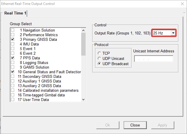
Set the update rate to 25Hz. This is preferred for Qinsy.
You could set it to 50Hz, but it is not preferred to go any higher than that.
Protocol
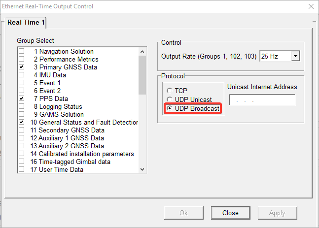
Select UDP Broadcast.
Qinsy - Setup
The example below can be found in the following template:
Note that the Geodetics are by default set to WGS `84 UTM 31N.
In case you want to use this template you will need to make sure the geodetics are changed to what you will use.
Port number and IP settings
Port number is fixed to 5602.
Therefore, if you have 2 POS-MV systems in your survey setup, you will need to enter an IP address.
This way Qinsy can work out which POS-MV you want to use.
In case you have 1 POS-MV in your setup, you don't need to enter in an IP address.
Slot values
For Position, Heading and MRU data we have 3 options:
|
Group |
Info |
QPS suggestion |
|---|---|---|
|
1 |
Vessel Position, Velocity, Attitude & Dynamics |
Not preferred since it does not contain heave |
|
102 |
Sensor 1 Position, Velocity, Attitude, Heave & Dynamics |
Preferred if POS-VIEW is set up like shown above |
|
103 |
Sensor 2 Position, Velocity, Attitude, Heave & Dynamics |
Could also be used if Sensor 2 is set up to output for the CoG |
Template - Position Navigation system
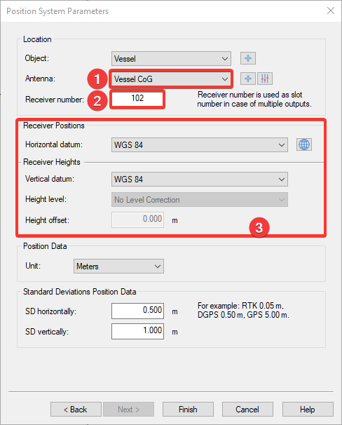
Add a Position Navigation System and select the "Network - POS MV V5 (Binary Groups 1/102/103)" driver.
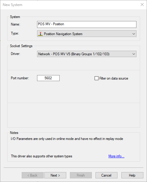
In case you have 2 POS MV systems in your network you can filter on IP. In a standard setup, this is not necessary.
-
Since the POS MV is now set up to output for CoG you can select Vessel CoG here.
-
Enter 102 as Slot value for Sensor 1 data
-
Make sure the correct datum is selected here.
Template - Gyro Compass
Add a Gyro Compass system and select the "Network - POS MV V5 (Binary Groups 1/102/103)" driver.
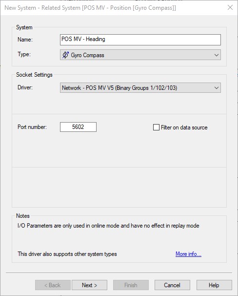
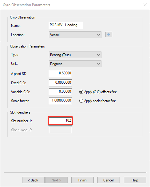
Enter 102 as Slot value for Sensor 1 data
Template - Pitch Roll Heave Sensor
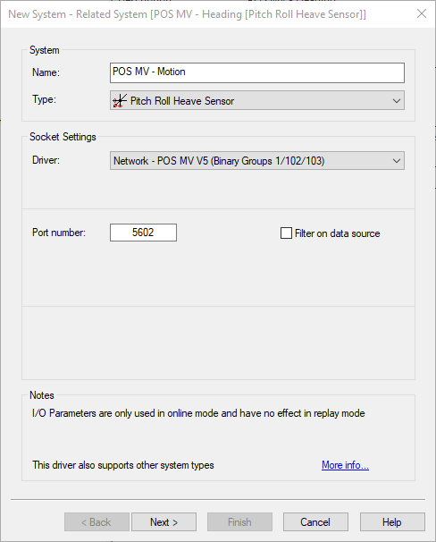
Add a Pitch Roll Heave sensor system and select the "Network - POS MV V5 (Binary Groups 1/102/103)" driver.
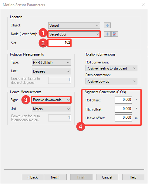
-
Since the POS MV is now set up to output for CoG you can select Vessel CoG here.
-
Enter 102 as Slot value for Sensor 1 data
-
Make sure that this is set to Positive downwards
-
These do not need to be entered since this should have been done in POS VIEW
Template - Miscellaneous - Status
Add a Miscellaneous system and select the "Network - POS MV V5 (Binary Groups 3/10/11/20 - Status)" driver.
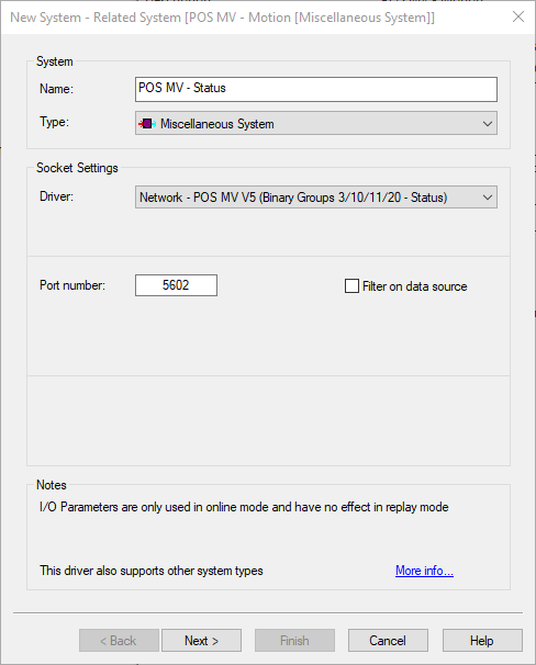
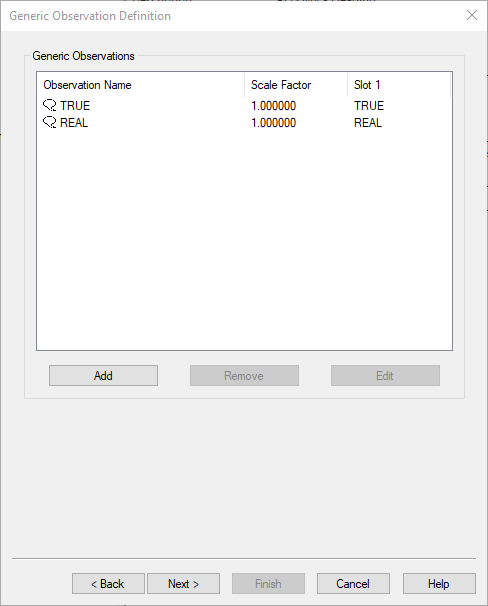
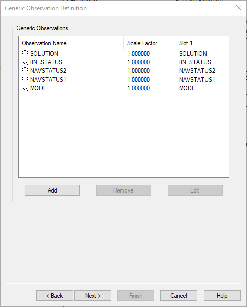
Make sure the following are added to decode the status of the POS MV:
Template - Time Synchronization
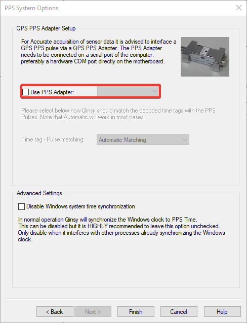
Add a Time Synchronization system and select the "Network - POS MV V5 (Binary Group 7 - PPS Time)" driver.
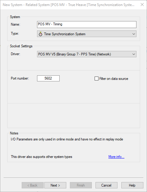
In case a PPS is interfaced with the Qinsy survey PC it can be added here.
In case all sensors in your setup have a Pulse and Timetag interfaced, you don't need to interface a Pulse with Qinsy and you can leave this unchecked.
Template - Miscellaneous - True Heave (extra)
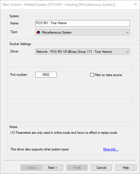
Add a Miscellaneous system and select the "Network - POS MV V5 (Binary Group 111 - True Heave)" driver.
Make sure the following are added to decode the status of the POS MV: