
Cable/Pipe Lay
Cable/Pipe Lay Results are not available for Export
| Parent Item | |
|---|---|
Cable/Pipe Lay
|
If you can't find this shortcut, make sure that option 'Show Cable/Pipe Lay Setup' is enabled in pull-down menu Settings, Session Shortcuts.
| Sub Item | Description | Value type | Properties |
|---|---|---|---|
Status | Value will be 1 or 0. 1 (one) when a Touchdown Method has been selected (Controller Session Setup, Cable/Pipe Lay) and 0 (zero) when the Touchdown Method is set to [ None ]. | integer | |
Time | Time of the last touchdown event | time | |
| Age | Elapsed time in seconds since the last touchdown event. | double | |
Node Name | The name of the selected bargetrack node, as entered in Database Setup. | text | |
Node Easting | Easting of the selected node (and computation) and is always on Survey Datum. | double | |
Node Northing | Northing of the selected Node (and computation) and is always on Survey Datum. | double | |
Node Latitude | Latitude of the selected Node (and computation) and is by default on Survey Datum, but WGS84 can also be selected. | geo | |
Node Longitude | Longitude of the selected Node (and computation) and is by default on Survey Datum, but WGS84 can also be selected. | geo | |
Distance Across | The value will be the Distance Across of the selected Bargetrack Node on the calculated Bargetrack route. | double | |
Speed Across | The value will be the Speed Across of the selected Bargetrack Node (using SOG and COG parameters) on the calculated Bargetrack route. | double | |
Speed Along | The value will be the Speed Along of the selected Bargetrack Node (using SOG and COG parameters) on the calculated Bargetrack route. | double | |
Layback Range | The layback range is calculated using the X and Y observation from the selected USBL system (Controller's Session Setup, Shortcut Cable/Pipe Lay). The used layback range is always an horizontal range, the Z observation from the USBL system is not used. | double | Range:
|
Layback Delta Height | The delta height value is the Z observation from the selected USBL system (Controller's Session Setup, Shortcut Bargetrack). | double | |
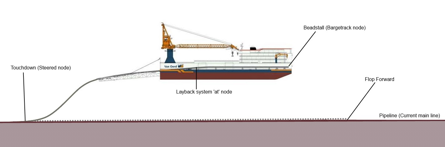 | |||
| Touchdown Method | The selected Touchdown Method as selected in the Controller's Session Setup, Cable/Pipe Lay page. | text | |
| Touchdown Id | Unique incrementing counter at every touchdown event | integer | |
| Touchdown Easting | Co-ordinate always on Survey Datum | double | |
| Touchdown Northing | Co-ordinate always on Survey Datum | double | |
| Touchdown Depth | The depth is by default on Actual Water Level but Chart Datum (also known as Vertical Datum) can also be selected using the Datum property | double | |
| Touchdown DX | double | ||
| Touchdown KP | double | Notice the additional Nr Format Property: "Station+Offset (US notation)". This will format a KP value as a Station+Offset (USA notation), where Station is the value in survey units * 100 and the Offset the remainder (in survey units). E.g 2345.6 feet along a route becomes 23+45.6. | |
| Flop Forward Easting | Easting of the calculated flop forward location. Always on Survey Datum. | double | |
| Flop Forward Northing | Northing of the calculated flop forward location. Always on Survey Datum. | double | |
| Flop Forward KP | The value will be the Kilometer Point of the calculated flop forward location on the pipeline (current mainline). | double | Notice the additional Nr Format Property: "Station+Offset (US notation)". This will format a KP value as a Station+Offset (USA notation), where Station is the value in survey units * 100 and the Offset the remainder (in survey units). E.g 2345.6 feet along a route becomes 23+45.6. |
| Flop Forward Length | The slant range of the layback value plus the offset to the beadstall node. | double | |
| Bottom Tension | The horizontal or vertical tension at the bottom (touchdown location) of the pipe or cable. Unit is the same as in the given weight in air / water of the pipe or cable. The horizontal component of the tension is always constant from touchdown point all the way to the release point, therefore this value is equal to the horizontal release tension | double | Reference:
|
| Release Tension | The horizontal or vertical tension at the release point of the pipe or cable. Unit is the same as in the given weight in air / water of the pipe or cable. The horizontal component of the tension is always constant from touchdown point all the way to the release point, therefore this value is equal to the horizontal bottom tension. | double | Reference:
|
| Curvature Radius | The value will be the minimum curvature radius. | double | |
| Error Code | Value 0 means no error. | integer | |
| Error Message | text | ||