ADCP
| Parent Item | |
|---|---|
| System: | List with all available ADCP systems that exist in the currently selected Qinsy database. (See General Layout Information about loading a Qinsy database). |
| Cell Number: | This option to select a cell number is only needed for possible selected cell sub items (e.g. Cell Number, Cell Depth, Cell Velocity)
|
| Computation: | This option to select a computation is only needed for possible selected ADCP sensor location sub items (e.g. Node Easting, Node Northing, Node SOG, etc.)
|
| Sub Item | Description | Value Type | Properties | ||||||||||||||||||||||||||||||
|---|---|---|---|---|---|---|---|---|---|---|---|---|---|---|---|---|---|---|---|---|---|---|---|---|---|---|---|---|---|---|---|---|---|
| Comment | User defined text. | text |
| ||||||||||||||||||||||||||||||
| Name | Name of the selected ADCP system, as defined in Db Setup. | text | |||||||||||||||||||||||||||||||
| Ping Time | Time of the last ping. | time | |||||||||||||||||||||||||||||||
| Cell Count | The number of depth cells that the current ping consist of. | integer | |||||||||||||||||||||||||||||||
| Cell Length | Instrument Setup setting. The depth range for each depth cell. | double | |||||||||||||||||||||||||||||||
| Pings Per Ensemble | Instrument Setup setting. Number of internal pings used for one update. | integer | |||||||||||||||||||||||||||||||
| Ping Number | Increasing number. Every new ping received from the ADCP sensor will increment the ping number by one. | integer | |||||||||||||||||||||||||||||||
| Ping Age | The difference between the triggering time and the time of the last ping in seconds.
| double | |||||||||||||||||||||||||||||||
| Beam Angle | Instrument Setup setting. Value in degrees. | double | |||||||||||||||||||||||||||||||
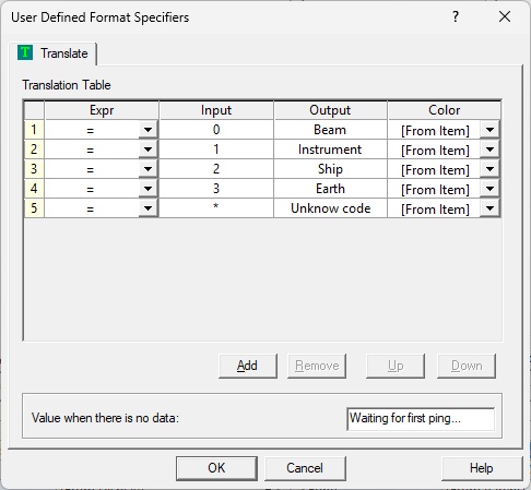
| Coordinate System | Flag that represents the current selected coordinate system for the individual velocity values. 0 means velocities per individual beam 1 Velocities relative to the ADCP instrument (X, Y, Z direction) 2 Velocities relative to Object (Ships Starboard/Forward,Mast direction) 3 Velocities relative to Earth (Easting, Northing, Up direction) | integer | You may define a translation table in order to translate the number codes into readable text.
| ||||||||||||||||||||||||||||||
| Node Name | Name of the node, as entered in Db Setup, for the ADCP sensor location. | text | |||||||||||||||||||||||||||||||
| Node Easting | The easting of the ADCP node, as calculated by the selected computation. The easting is always on Survey Datum. | double | |||||||||||||||||||||||||||||||
| Node Northing | The northing of the ADCP node, as calculated by the selected computation. The northing is always on Survey Datum. | double | |||||||||||||||||||||||||||||||
| Node Latitude | The latitude of the ADCP node, as calculated by the selected computation. Latitude is default on Survey Datum, but WGS84 (or ITRF2008) can also be selected. | geo | Datum:
| ||||||||||||||||||||||||||||||
| Node Longitude | The longitude of the ADCP node, as calculated by the selected computation. Longitude is default on Survey Datum, but WGS84 (or ITRF2008) can also be selected. | geo | Datum:
| ||||||||||||||||||||||||||||||
| Node Height | The height of the ADCP node, as calculated by the selected computation. Height is by default on Chart Datum, but Survey Datum, WGS84 (or ITRF2008), the Actual Water Level, the Mean Water Level, or the Geoid Model Level may be selected. | double |
| ||||||||||||||||||||||||||||||
| Node SOG | The speed over ground for the node location of the ADCP sensor. Notice that the SOG depends on the Controller's Computation Setup, Object COG/SOG - Prediction Parameters Settings. | double | Unit:
| ||||||||||||||||||||||||||||||
| Node COG | The course over ground of the object on which the ADCP node is located. | double | Reference:
| ||||||||||||||||||||||||||||||
| Node Heading | The heading of the object on which the ADCP node is located. If the object does not have a valid heading, then the (COG + Convergence) will be displayed. | double | Reference:
Rotation:
| ||||||||||||||||||||||||||||||
| Cell Number | The selected cell number. | integer | |||||||||||||||||||||||||||||||
| Cell Depth | The depth for the selected cell number. | double | |||||||||||||||||||||||||||||||
| Cell Velocity | One of the beam velocities for the selected cell number. Use the Parameter property to select for which beam you want to see the velocity. Further, the velocity value is a raw value, and its reference depends on the selected coordinate system. | double |
| ||||||||||||||||||||||||||||||

