
How-to Update Geoid Models.xml
This How-to describes how to add a new geoid model to the *.xml file.
On this page:
Example of adding Vertical Datum GTX file
Follow this series of steps to add a model:
- If you need to add a model for North America, download it from: https://vdatum.noaa.gov/download.php (here we used Tidal Datum MLLW Gulf of Maine - NAVD88 as example)
- Place the downloaded model in the following folder: C:\Users\Public\Public Documents\QPS\Shared\Geo\Geoid
- Check your C-drive for an existing GEOIDMODELS.xml at C:\Users\Public\Public Documents\QPS\Shared\Geo\Geoid
- If the *.xml file is not available, copy it from where Qinsy installs the latest files at C:\Program Files (x86)\Common Files\QPS\Geo\Geoid (the file in this location is overwritten every time a new version is installed)
- Open the GEOIDMODELS.xml under the Shared folder (the file in this location is not overwritten every time a new version is installed)
- Copy a block with a geoid model that is similar to the one you are going to add
- Paste this block somewhere in the file
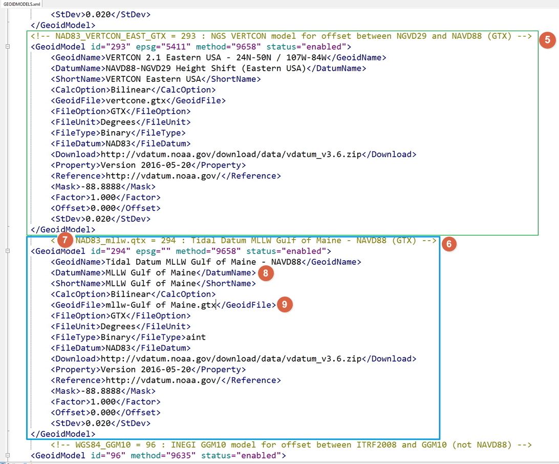
- Enter a unique id value (294 in this example)
- Enter a name for the new model at GeoidName, DatumName and ShortName
- Enter the GeoidFile name (the copied file at point 2)
- If the model format is already supported and available in Qinsy, then no additional steps are required
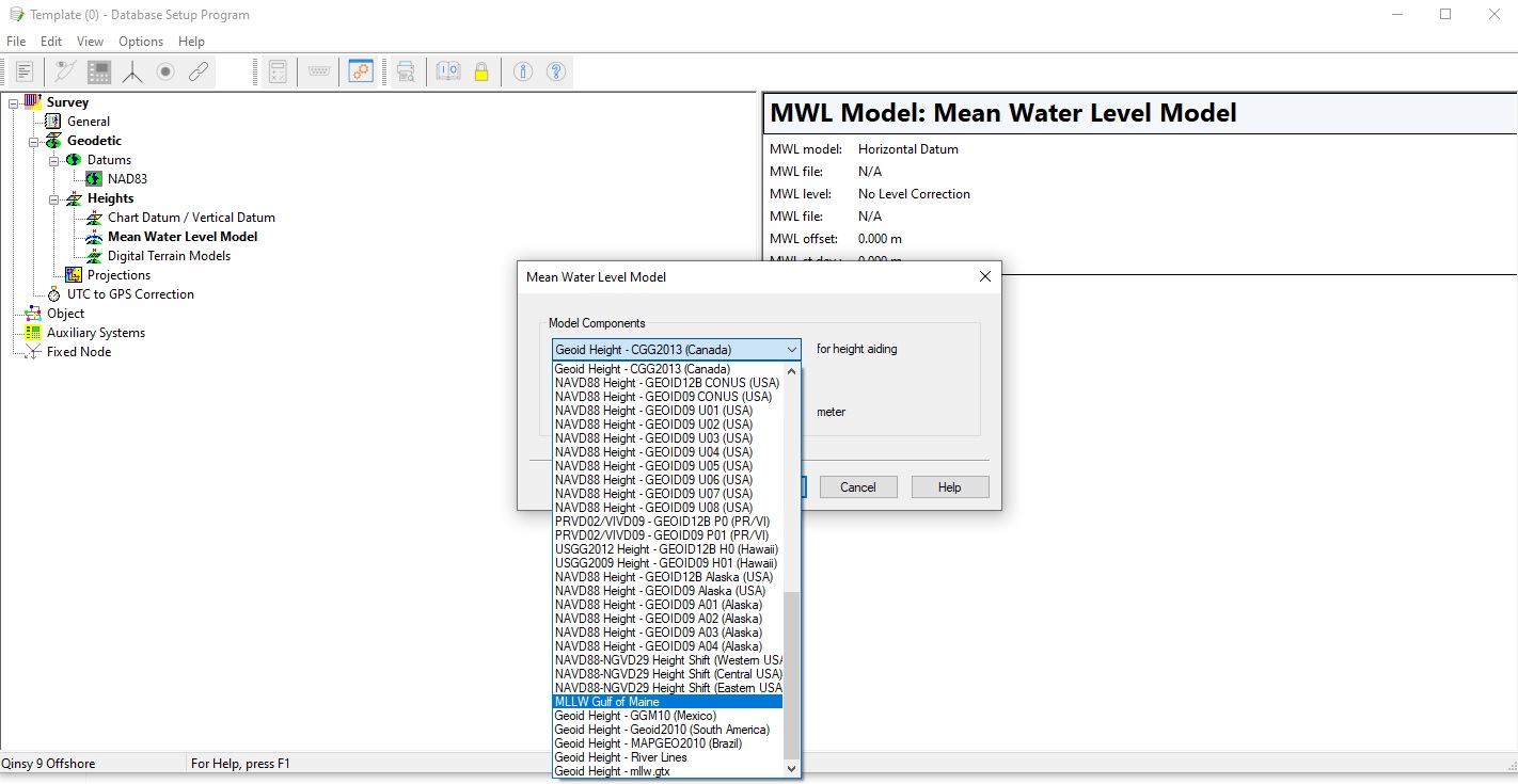
- Now you can select this model in the Database Setup
Detailed XML description
Qinsy geoid model files
Most geoid models are available as ASCII files containing height values on a regular geographical grid.
In order to obtain the necessary real-time file seeking speed, Qinsy can only use binary files in "LLDLLD" or "NGS" format, except for DLL's or river line models.
Files in other formats must therefore be converted using the Geoid Model Utility which can be found in the Qinsy Console.
A geoid file must be a rectangular grid (except for river models), but may contain a so-called mask: grid points where the geoid heights are not defined.
Such geoid heights must be indicated by values less than -999 or larger than 999.
Most geoid files must contain geoid heights on coordinate lines starting at the northern-most latitude (or northing) going from west to east, until the southern-most latitude (or northing), i.e. from the north-west corner to the south-east corner.
One exception is the binary grid file format from NGS, which starts at the south-west corner, going from south to north.
The other exception to this rule are the geoid files containing river models, defined along one or more survey lines.
If the format is not given in this list, please contact QPS Support to see what the possibilities are.
Update GEOIDMODELS.XML file
The various geoid and height level models that are available in Qinsy are defined in GEOIDMODELS.XML, which is located in the <\Geoid > subdirectory of the Qinsy installation directory (e.g. <C:\Program Files (x86)\Common Files\QPS\Geo\Geoid>).
This directory is updated with every new release of Qinsy and contains the most recent models.
However, your project may be looking at the following path: <C:\Users\Public\Public Documents\QPS\Shared\Geoid>.
The XML file, using the well-known Extensible Markup Language format, can be edited to add another geoid model.
Where to store your Geoidmodels.xml
When editing the models.xml, make sure to keep a copy in the Shared folder, as the one in the Common Files will be overwritten when an update is applied.
See below for an example of a geoid definition:
<!-- NAD83_VERTCON_WEST_GTX = 291 : NGS VERTCON model for offset between NGVD29 and NAVD88 (GTX) -->
    <GeoidModel id="291" epsg="5409" method="9658" status="enabled">
        <GeoidName>VERTCON 2.1 Western USA - 24N-50N / 125W-102W</GeoidName>
        <DatumName>NAVD88-NGVD29 Height Shift (Western USA)</DatumName>
        <ShortName>VERTCON Western USA</ShortName>
        <CalcOption>Bilinear</CalcOption>
        <GeoidFile>vertconw.gtx</GeoidFile>
        <FileOption>GTX</FileOption>
        <FileUnit>Degrees</FileUnit>
        <FileType>Binary</FileType>
        <FileDatum>NAD83</FileDatum>
        <Download>http://vdatum.noaa.gov/download/data/vdatum_v3.6.zip</Download>
        <Property>Version 2016-05-20</Property>
        <Reference>http://vdatum.noaa.gov/</Reference>
        <Mask>-88.8888</Mask>
        <Factor>1.000</Factor>
        <Offset>0.000</Offset>
        <StDev>0.020</StDev>
    </GeoidModel
Copy this datablock and add it to the existing GEOIDMODELS.XML file and edit as described below:
The lines between <GeoidData> and <DataDatum> define the properties of the ‘input data file’ during the geoid model creation.
They are not required for Qinsy Online and Replay sessions.
The other lines describe the 'output data file' properties for the conversion and are also used by Qinsy Online and Replay.
<?xml version="1.0" encoding="UTF-8" standalone="yes"?> and <GEOIDMODELS> are required.
Absolute or Relative and their ID's
<GeoidModel id="100" status="enabled">Absolute geoid models are defined between:
- <GeoidModel id="XXX" status="XXX"> and </GeoidModel> pairs and have ID's between 0 and 999.
Relative geoid models, height level correction models, are defined between:
- <LevelModel id="XXX" status="XXX"> and </LevelModel> pairs and have ID's between 1000 and 9999.
ID values must be unique since they are used by Qinsy to save the selected geoid model(s) in the database and to retrieve the model settings for an Online or Replay session.
Some geoid and level models are required, denoted by status="fixed", i.e.
Description | id= "XXX" (=ID) | status="XXX" |
|---|---|---|
Undefined or Horizontal Datum | 0 | |
Manual Height Offset | 1 | |
User defined GeoidModels | 100 - 199 (preferred range) | |
Predefined or user-defined models | 2 - 899 | |
Geoid Height - QGF Vertical Offset Model | 900 | |
No Height Level Correction Applied | 1000 | |
User defined height LevelModels | 1100 - 1199 (preferred range) | |
Predefined or user-defined models | 1001 - 1899 | |
Height Level - QGF Vertical Offset Model | 1900 | |
To show the model from Database Setup | enable | |
To hide the model from Database Setup | disabled |
Absolute geoid models are defined between <GeoidModel id=”XXX” status=”XXX”> and </GeoidModel> pairs and have ID’s between 0 and 999.
Relative geoid models, height level correction models, are defined between <LevelModel id=”XXX” status=”XXX”> and </LevelModel> pairs and have ID’s between 1000 and 9999.
Use 100 to 199 and 1100 to 1199 for user-defined models.
GeoidModel id
If you add your own geoid model, it’s important that you choose an ID that doesn’t exist yet.
For an absolute geoid model, choose an ID between 100 and 199.
For a relative height level model, choose an ID between 1100 and 1199.
Name
<GeoidName>Local Geoid Height Model - QPS (Local/Bilint)</GeoidName>
<DatumName>Geoid Height - QPS (Local/Bilint)</DatumName>
<ShortName>QPS (Local/Bilint)</ShortName>
<GeoidName>, <DatumName> and <ShortName> are used for the description of the geoid model, respectively for very long, long and short names.
These XML tags are required, otherwise the default names for model "0" are shown.
Enter the names of the model you are adding.
These names are shown in the Mean Water Level selection list in Database Setup.
Interpolation option
<CalcOption>Bilinear</CalcOption> <CalcOption> determines how a geoid height is calculated from the geoid model file.
Options are:
- Spline - spline interpolation using 16 points (4 by 4 window around the current position),
- Bilinear - linear interpolation using 4 points around the current position,
- DLL - using the DLL function that is given between the <CalcFunction> pairs (not applicable for local user-defined geoid models).
<CalcFunction> and <MinMaxFunction> tags are only used in case of DLL models (<CalcOption> "DLL").
File name and options
<GeoidFile>GEOID-BILINT.BIN</GeoidFile>
<FileOption>LLDLLD</FileOption>
<FileUnit>Degrees</FileUnit>
<FileType>Binary</FileType>
<FileDatum>WGS84</FileDatum>
<GeoidFile> gives the name of the actual geoid model file that is to be used Online or during Replay.
This would preferably be "bin" for a binary grid data file.
It must be "dll" for a DLL and "pro" for a river line model in a PRO file.
<FileOption>, <FileUnit>, <FileType> and <FileDatum> give the properties for the actual geoid model file that can be used by Qinsy and also for the 'output data file' that is created using the Geoid Model Utility.
<FileOption> indicates the file format.
Among the currently implemented options are:
- LLDLLD, binary grid heights preceded by a header containing
- minimum latitude, maximum latitude, delta latitude,
- minimum longitude, maximum longitude, delta longitude,
- NGS, binary grid heights preceded by a header in the National Geodetic Survey format, as well as
- DLL, for DLL's
<FileUnit> gives the unit for the header values, which would be
- "Degrees" or "Seconds" for geographic positions
- "Meters" or "Units" for the river models in the PRO file format.
<FileType> is always
- "Binary".
<FileDatum> must be
- "WGS84",
- "ITRF",
- "GRS80",
- "NAD83",
- "ETRS89"
- or empty for survey datum.
WGS84 and ITRF are equivalent datums, and so are GRS80, NAD83 and ETRS89.
Input file information
<GeoidData>GEOID.TXT</GeoidData>
<DataOption>LLH</DataOption>
<DataUnit>Degrees</DataUnit>
<DataType>Text</DataType>
<DataDatum>WGS84</DataDatum>
<Mask>-999</Mask>
<GeoidData> gives the name of the data file that is to be used to convert a geoid model using the Geoid Height Utility in order to create a binary geoid model file that can be used Online or during Replay.
This would be an ASCII data file or a binary data file in a format that is not supported by the other Qinsy modules (which do not use this and next tags).
<DataOption>, <DataUnit>, <DataType> and <DataDatum> give the properties for the 'input data file' to be converted.
They are not required for Qinsy Online or Replay.
<DataOption> indicates the input file format.
Among the currently supported options are:
- LLDLLD - ASCII geoid heights on a geographical grid preceded by a header containing:
- minimum latitude, maximum latitude, delta latitude,
- minimum longitude, maximum longitude, delta longitude,
- LLLLDD - geographical grid heights preceded by a header containing:
- minimum latitude, maximum latitude,
- minimum longitude, maximum longitude, delta latitude, delta longitude,
- LLH - geographical grid heights in lines containing:
- latitude, longitude, geoid height,
- EEDNND - ASCII geoid heights on a grid projection preceded by a header containing:
- minimum easting, maximum easting, delta easting,
- minimum northing, maximum northing, delta northing,
- EENNDD - projection grid heights preceded by a header containing:
- minimum easting, maximum easting,
- minimum northing, maximum northing,
- delta easting, delta northing,
- ENH - projection grid heights in lines containing:
- easting, northing, geoid height,
- IFE - binary grid heights preceded by a header in a format used by the Institut fuer Erdmessung (Hannover, Germany),
- NGS - binary grid heights preceded by a header in the National Geodetic Survey format,
- LINE - grid heights along one or more survey lines on the survey projection, in various formats
- just ASCII easting, northing, height,
- formats as used by Kongsberg Simrad, Germany
- SZ Dateien, Germany.
<DataUnit> gives the unit for the header values, which would be:
- Degrees or Seconds for geographic positions and
- Meters or Units for projection grid coordinates
<DataType> can be
- Text or Binary.
<DataDatum> must be:
- WGS84
- ITRF
- GRS80
- NAD83
- ETRS89
- or empty for Eastings and Northings on the survey datum.
The information contained in <Download>, <Property> and <Reference> are just for administrative purposes.
<Mask> indicates which value is used by the geoid model to indicate 'masked grid points' where the geoid height is not known.
A zero mask value means that no masking is used.
Masking is used to outline the shape of for example a country within a rectangular grid.
Positions in a 'masked' grid cell (and indeed outside the rectangular grid boundaries) should return an error (or use interpolation between one to three non-masked grid points).
<Factor> and <Offset> are currently only used during geoid file conversion.
<Factor> can be used to multiply the input geoid height, for example to convert mm to meters (0.001).
<Offset> can be used to add or subtract an offset.
<StDev> is used in the TPE (Total Propagated Error) calculations in the MultiBeamer. Enter a 1-sigma error value.
Model not visible
If the status attribute in the <GeoidModel> tag or the <LevelModel> tag is changed to "disabled", the model will not be visible anymore in any geoid model selection combo box.
The same will be the case when the model file is missing.