How-to Time Synchronization Display
This How-to describes the Time Synchronization functionality.
General
A Time Synchronization System is used to synchronize the internal Qinsy clock and the Microsoft Windows system clock to UTC time.
In Qinsy the name PPS (Pulse Per Second) was commonly used to refer to time synchronization of the internal Qinsy clock to UTC.
All the incoming data that does not have its own UTC timetag is timestamped in the driver, based on this internal Qinsy clock.
Naming background: PPS is a slightly old fashioned name; there are many more possible ways to synchronize the Qinsy clock, e.g. NTP, serial string, etc. The display is named DspTimeSync.
Only a single Time Synchronization system is allowed per template.
Time synchronization can be very accurate (better than 0.5 milliseconds) when using a Qinsy Time Synchronization Adapter which interfaces a TTL 1 pulse per second (Time Synchronization) signal from a GPS receiver into the computer.
If this is not used, an averaging of incoming time tags is used; this will be less accurate but stable.
Surveying without the Time Synchronization Adapter should only be done when the timing requirements are not so strict, e.g. because all timing critical sensor data is already UTC time tagged in the system itself or when no multibeam sounders are used.
In Database Setup the Time Synchronization system can be defined in a wizard with two pages: the first page will set up what type of time tag is used (e.g. ZDA GGA NTP) and on which port it is arriving, on the second page the COM port of the Time Synchronization Adapter can be selected.
For more info on the Time Synchronization adapter refer to the Knowledge Base article under header Hardware - QPS Fix Boxes: 'QPS PPS and Fix Adapter'.
On this page:
MSWindows Clock synchronization
While online with the Controller the MSWindows Clock is synchronized every time it deviates from the internal Qinsy clock more than a hard coded offset (a couple of milliseconds).
Although Qinsy could run without a properly synchronized clock, it is strongly advised to keep this enabled because there are some drivers that rely on it, for example the Klein 3000/3900/5000 driver.
The only valid reason to disable synchronization is when another program is setting the MSWindows Clock already and it's operation is interfered by Qinsy.
This can, for example, happen when one computer is shared by Qinsy and the Reson 7K topside software.
In that case, please use the driver: 'Third Party synchronized Windows system time - 18' listed in the Drivers Manual.
Time Sync modes of operation
In general there are two modes for time synchronization:
- Time tags only
When a time tag arrives, it is assumed that it reports the UTC time that it was transmitted. Note that any deviation from this rule will result in a time offset. Around 60 seconds of incoming time tags are maintained in a buffer. A mean arrival time is calculated from it to guarantee a steady Qinsy clock.
If you are using only a GGA/RMC/GGK string without pulse, this may be subject to latency in the GPS receiver, again resulting in a time offset. Therefore it is advised to always use a Time Synchronization pulse for accurate timing.
- Time tags and Time Synchronization Pulses
Two consecutive pulses are used to calculate a very steady Qinsy clock. Time tags are matched automatically to the pulses, based on their arrival times.
For accurate time synchronization we advise to always use a QPS Time Synchronization adapter since this is by far the most accurate method. NTP is second best and can be reasonably accurate for local networks.
Estimated time synchronization accuracies
How accurate the time synchronization will be, depends on the type of synchronization.
Below, a table with typical accuracies is shown.
These are estimates and depending on the situation they may be worse or better.
| Type | Estimated Accuracy (milliseconds) |
|---|---|
| Time Synchronization Adapter + Time tag | < 0.5 |
| SNTP (Simple Network Time Protocol) | < 2 (local network) |
| NMEA ZDA time tag serial/or network UDP | < 5 |
| NMEA GGA/GGK/RMC | Depends on output latency of GPS |
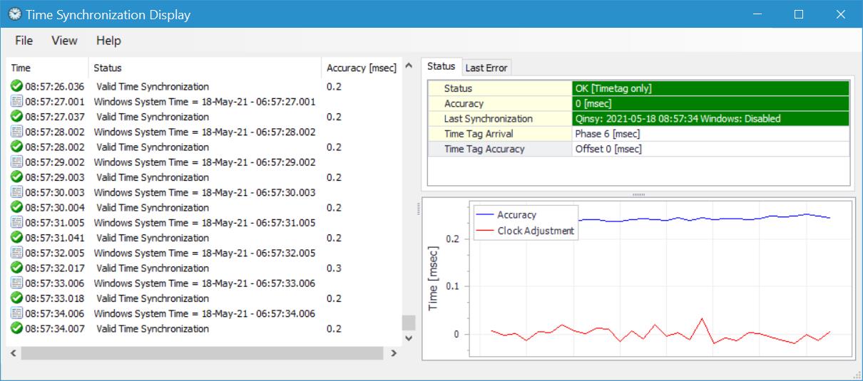
Time Synchronization Display
The TimeSync display is divided into three panes:
- (LEFT) The event list which will show the incoming time tags, pulses and Time calculation results.
- (TOP RIGHT) Status grid and Last Error grid pane. This shows the current status of the Qinsy and MSWindows time.
- (BOTTOM RIGHT) The chart pane. This will show a time plot of the various parameters.
The look of the panes can be customized by the user through the View - Preferences dialog or by right-clicking with the mouse pointer.
Size, position and the customized options will be stored in an *.xml file (in Local App Data).
In the following paragraphs the panes will be described in more detail.
Event List pane
The event list view will show a chronological overview of incoming time tags, Time Synchronization pulses and time calculation results.
The view contains three columns, from left to right: the time an event occurred, the description of the event and the accuracy (only for time sync result).
Each type of event has its own icon:


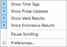
With the right mouse button over the list view a selection can be made of the types that are shown (see also the View - Preferences dialog).
You can also pause scrolling through this menu in case an event needs a closer inspection.
Status Grid pane
The status grid shows various info about the time synchronization.
With different colors (Green, Red, Orange) it will indicate its status. 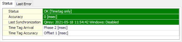
Status
This shows the status of the last time that a sync calculation was carried outOK [Matching method] Time Sync working fine (Green color) Error [Matching method]
An error occurred (Red) The Matching method reflects the Pulse Timetag matching method from Database Setup and can be one of the following strings:
- Time Tag Pulse Auto Matching,
- Time Tag Before Pulse,
- Time Tag After Pulse,
- Time Tag Only.
Accuracy
This will indicate the accuracy of the time synchronization.
When a pulse is interfaced, the measured time between the pulses minus 1 second is a measure for accuracy.
For time tag only mode, the accuracy is determined by the variation in arrival of the time tag messages.The color is determined by the accuracy:
Accuracy (msec) Color Meaning < 1 msec Green Excellent Accuracy > 1 and < 10 Orange Limited Accuracy > 10 Red (bad accuracy, investigate!) - Last Synchronization
Show the time the clock was last set for both the Qinsy clock and the Windows system clock.
For Qinsy in principle every time a valid time sync is calculated, the Qinsy internal clock is updated.
The Windows system clock is only set when it starts to deviate from the Qinsy clock.- If the synchronization of the Windows system time was disabled in the setup then it will show "Disabled".
Green Color indicates success,
Orange color indicates that the Windows clock could not be set. This can happen if the current user has limited user rights and therefore the API call SetSystemTime fails.
If this occurs set administrator rights for the user account:
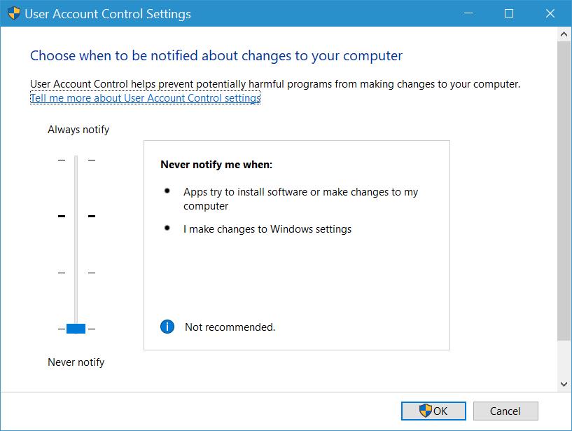
UAC in Windows 10
Make sure to move the slider to 'Never notify'.
- Time Tag Arrival
This shows the number of milliseconds that the time tag that was matched to the Time Synchronization pulse arrived before or after the pulse occured.
(When no Time Synchronization Adapter was interfaced, it shows the arrival with respect to the Qinsy clock zero-second crossing).
For example, if a time tag arrives 100 milliseconds before the pulse then this shows "100 [msec] before the pulse".
If it arrives half a second after the pulse this shows: "500 [msec] after the pulse".
Time Tag Accuracy
This is an interesting figure that gives an indication whether the reported time tag coincides with the arrival time.
For accurate (e.g. NMEA ZDA) time tags the accuracy figure should be around zero.
For example, when the Timetag arrival is reported as 66 msec after the pulse, but the timetag in the NMEA ZDA has .000 seconds fraction, the Accuracy is reported as -66 milliseconds.Info
Note that when the Offset exceeds 400 milliseconds in automatic matching mode, the label is drawn in red.
This is to indicate to the user that the output timing of the string is not suitable for automatic pulse time tag matching mode.
Chart pane
The lower right pane shows a time plot chart.
The horizontal axis shows the current Qinsy clock time and a user defined history, on the vertical axis various parameters are plotted.
The range of the axes can be changed via the Options dialog.
The vertical axis can have an automatic scale or a fixed scale.
The following series can be presented:
| Accuracy | Estimated overall time accuracy. This only updates when no error occurred. |
| Clock Adjustment | This shows the value of the adjustment that was carried out on the Qinsy clock during the last update. This only updates when no error occurred. |
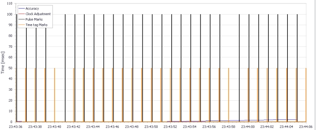
| Time tag Marks | Every time a time tag arrives, a marker (vertical line) is drawn in the chart (from 0-50 msec). This allows you to see the arrival relationship between pulse and time tag. |
| Pulse Marks | Every time a pulse arrives, a marker is drawn in the chart (from 0-100 msec). |
The series can be switched on/off in the View - Preferences dialog.
Note that in order to see the marks you should select a small horizontal time span.
See below for a screen shot.
The marks will usually only be selected for diagnostic purposes.
Note
It is strongly advised to limit the the horizontal time span to maximum 30 minutes for CPU and memory load considerations!
Preferences
Various options can be set via the Preferences dialog.
All options will be stored in an *.xml file upon closing and retrieved upon startup.
The *.xml file is stored in the Local Application Data folder.
An overview of the options:
- General
Show UTC or local times. This applies to all the times within the display. - List
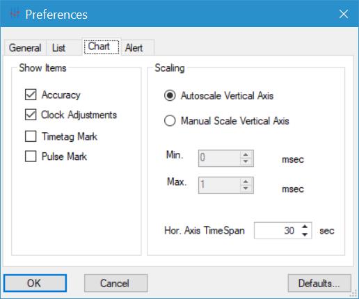
Show/hide various event types and also pause scrolling. Chart
Show/hide the series in the chart.
The vertical scaling can either use auto scaling or a user defined fixed scale.
For the horizontal scale a time span needs to be entered.Warning
Setting this time span higher than +/- 30 minutes can lead to higher CPU loads and memory load and is therefore only to be used for diagnostic purposes.
If you would like to view the pulse and time tag marks, set a very small time span otherwise the chart will be overcrowded.
- Alert
If an error condition occurs continuously, then after a user definable number of seconds the display will turn red and optionally pops up to indicate the error condition.
The options in all the tab pages are explained in more detail in the F1 Help file of the Time Synchronization Display.
Error Codes
In case the time synchronization did not succeed, an error message and code are shown.
Below an overview is shown of the possible errors and their possible solutions to apply if an error situation prolongs.
| Code | Message | Explanation | Solution |
|---|---|---|---|
| 1 | Unknown Error | An unknown error occurred. | This should not happen, contact QPS. |
| 2 | Counter not running | Very rare error, you motherboard is not suitable because it lacks a hardware counter. | Use another PC. |
| 3 | Counter frequency varies | The hardware counter reports a variable frequency. This can happen if your computer uses some form of CPU speed throttling, for example Intel Speed Step, AMD Cool'n'Quiet and PowerNow! technology. This will reduce the hardware counter frequency in order to save power*. | Disable speed throttling in BIOS*. |
| 4 | Wait for pulses | Only on startup, no Time Synchronization pulses have been received yet. | Check if the Time Synchronization Adaptor flashes, check pulse cabling. |
| 5 | No matching timetag found | Pulses are received, but time tags did not arrive around that time. | Check that the GPS reciever constantly outputs the timetags. |
| 6 | Time between pulses is wrong | The measured time between pulses should be exactly one second (within +/- 1 millisecond). | If this error occurs then possibly the serial port you used is not responsive enough to read the signal from the Time Synchronization Adaptor, for example a USB to serial convertor was used. The Time Synchronization Adaptor should be interfaced on a Hardware comport, best directly on the motherboard, or a pci card. Multi-serial cards that are approved for accurate time tagging (e.g. Moxa xx-168) can also be used. Another possible source for this error is again active CPU speed throttling*. |
| 7 | Missing Pulse | Time between two Time Synchronization pulses is around 2 seconds. This means a pulse was missed. | This can happen on USB serial ports. Install the Time Synchronization Adapter on a proper hardware serial port. |
| 8 | No Timetags received | No time tag was received for longer than 5 seconds. | Check connection and GPS receiver. |
| 9 | No Pulses received | No pulse was received for longer than 5 seconds. | Check if the Time Synchronization Adaptor flashes, check pulse cabling. |
| 10 | Wrong timetag interval | The time reported by the time tags fluctuates. | Check the GPS output settings, probably the output triggering is wrong. Ideally, the timetag in the output message coincides with the moment the first character of the message is transmitted. |
Tip
Always disable speed throttling in the BIOS of the motherboard!
Note
Errors 4, 5, 6, 7, 9, 10 can only occur if a Time Synchronization Adaptor is used.
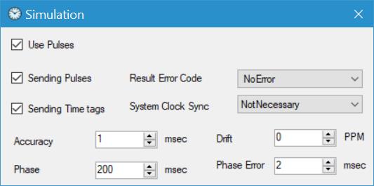
Simulation mode
For training or testing purposes, the display can be started stand-alone. It will start a simulation automatically.

Via a mode-less dialog various scenarios can be simulated, the display will respond immediately to the changed parameters.