
How-to Set up a Local Engineering Coordinate System
This document describes how to set up a Local Engineering Coordinate System (previously named Local Construction Grid) in the Geodetic Parameters of the Geodetic User Interface.
An engineering grid is used to create a local grid on top of the map projection grid.
This can be used to define a local grid for dredging projects, an engineering grid for a plant or harbor, or a local grid to correct the map projection, for example to convert coordinates from Eastings-Northings in the Transverse Mercator (South Hemisphere) projection to Westings-Southings in the Transverse Mercator (South Oriented) projection.
The local grid can be based on two methods of calculation: the Point and Azimuth method or the Two Common Points method.
On this page:
General
Local (Engineering) Grids date from the pre GNSS RTK era; the time that total stations were limited in the number of digits they could use.
At building sites on land people generally work with Total Stations and Level instruments, due to the high level of accuracy required. The local grid could also be used with static 3D laser scanning and local targets.
A local grid can only be used for a small area due to the fact that it represents a flat surface with fixed scale factors.
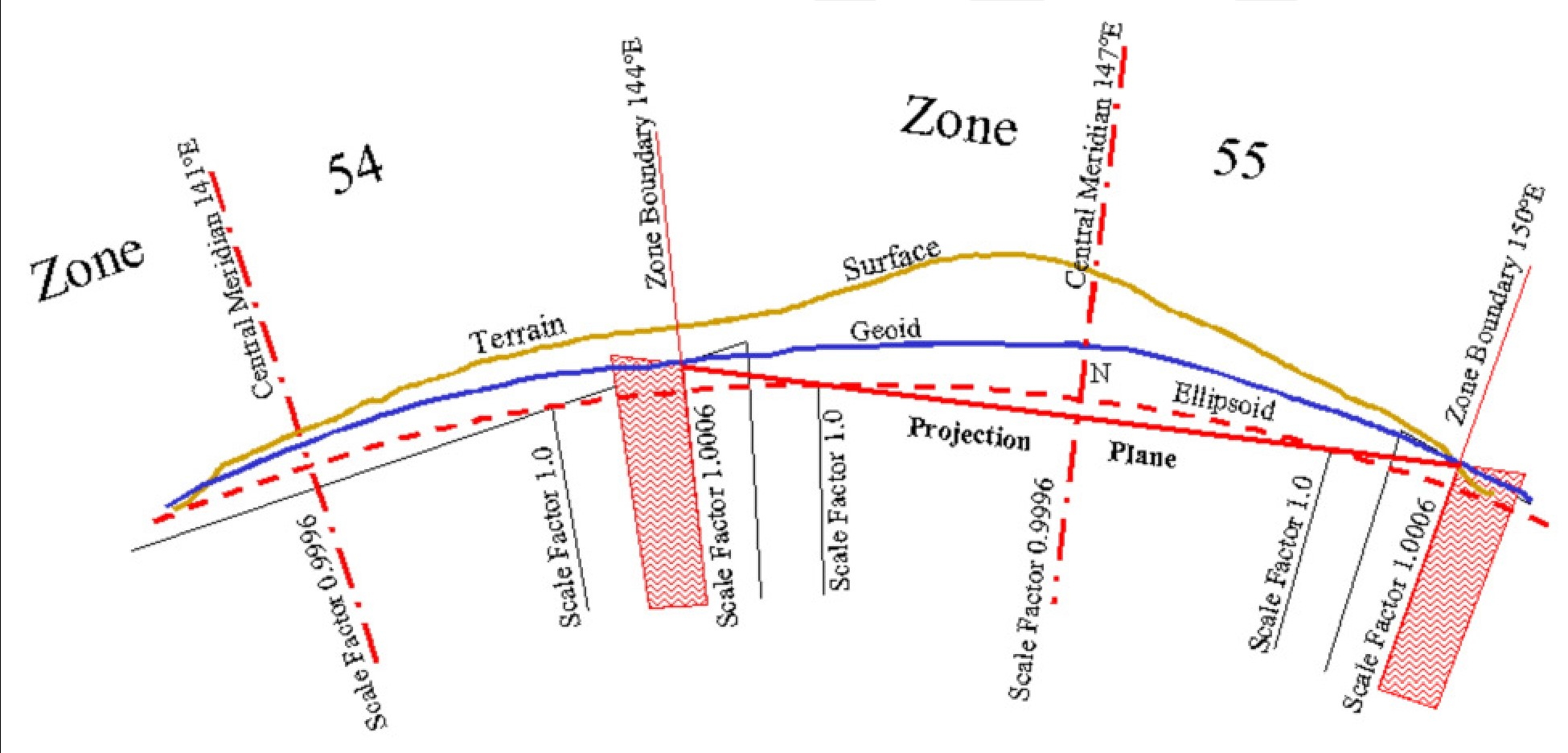
Scale factors for projections are variable:
Engineering Grid Parameters
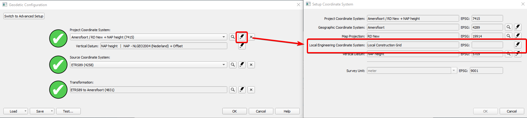
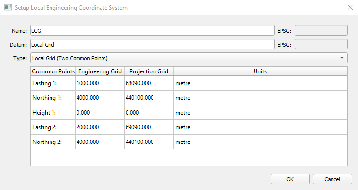
Enter the settings on the fourth page of the Geodetic Setup wizard in the Database Setup:
| Setup Local Engineering System | |
|---|---|
| Name | Enter a name for the local grid. |
| Datum | Enter a name for the local datum. |
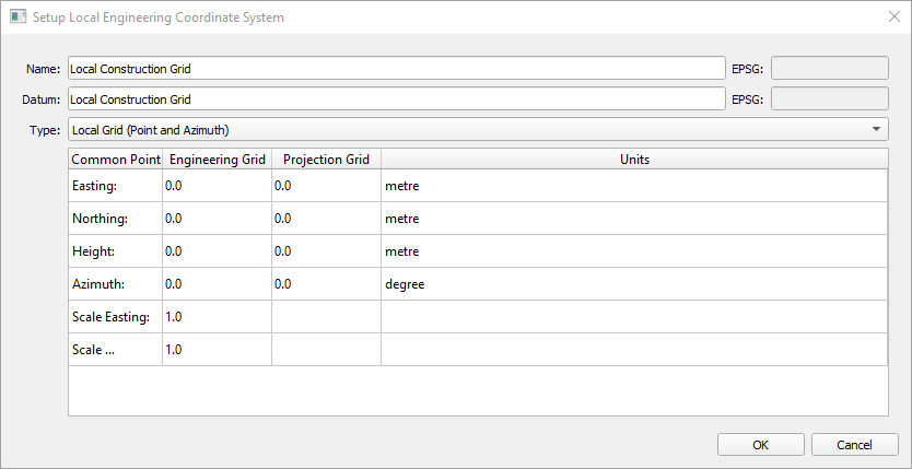
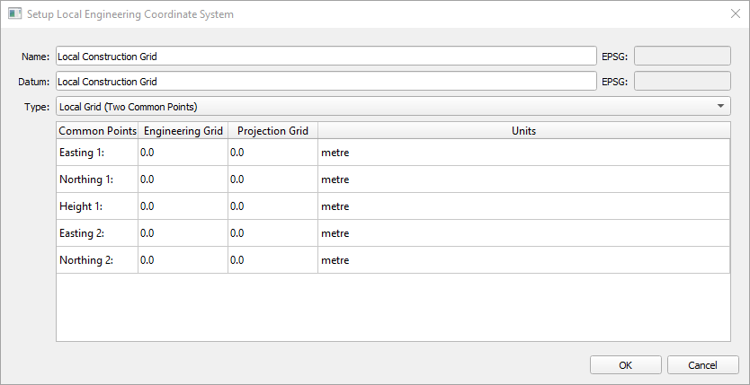
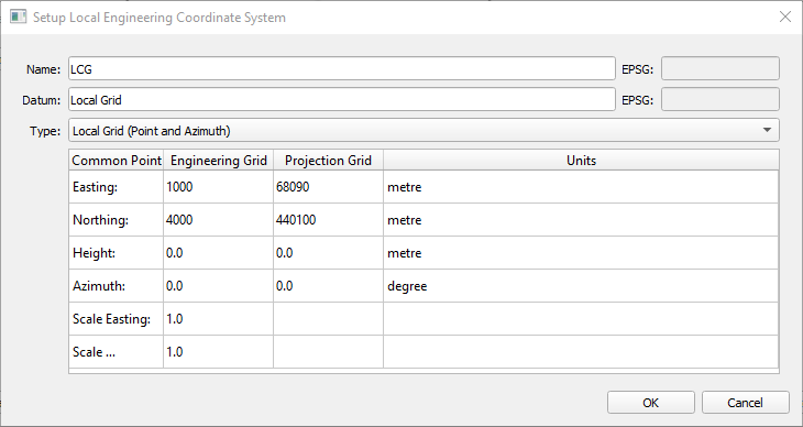
| Type |
|
Affects all Grid Coordinates
When using the Local Engineering Grid option all grid coordinates shown in Qinsy are on this local grid.
For example the Easting/Northing coordinates as shown in the Survey Manager and as shown in the various displays.
The geographic (Latitude/Longitude) coordinates, on the other hand, are always defined on the selected survey datum.
Example
Local Engineering Grid Setup
In this example we will set up a Local Engineering Grid at the Benelux Harbor in the Port of Rotterdam:
For this example we will use a predefined coordinate system for The Netherlands:
RDNAPTRANS 2008 ETRS89 to RD/NAP
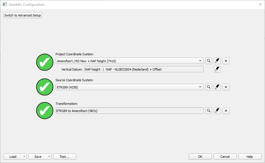
You can use any type of coordinate system you require, but you have to think about the scale factors at your location due to the used projection.
Before you start setting up a Local Engineering Grid, it is advised to check if your background data (QGF background, DXF, DWG) is in the projection coordinates and can be seen in the Survey Manager or Online in the Navigation Display.
Another thing you will need to check is if the points you want to use as a reference for your Local Grid are in the correct projection. You can use the “Test Geodetical Parameters” in the Geodetic User Interface to check the coordinates.
If you created lines for the X and Y axis of your Local Grid, you could also use these as a KP and Offset Grid (KOG), but you have to be aware of scale factors again.
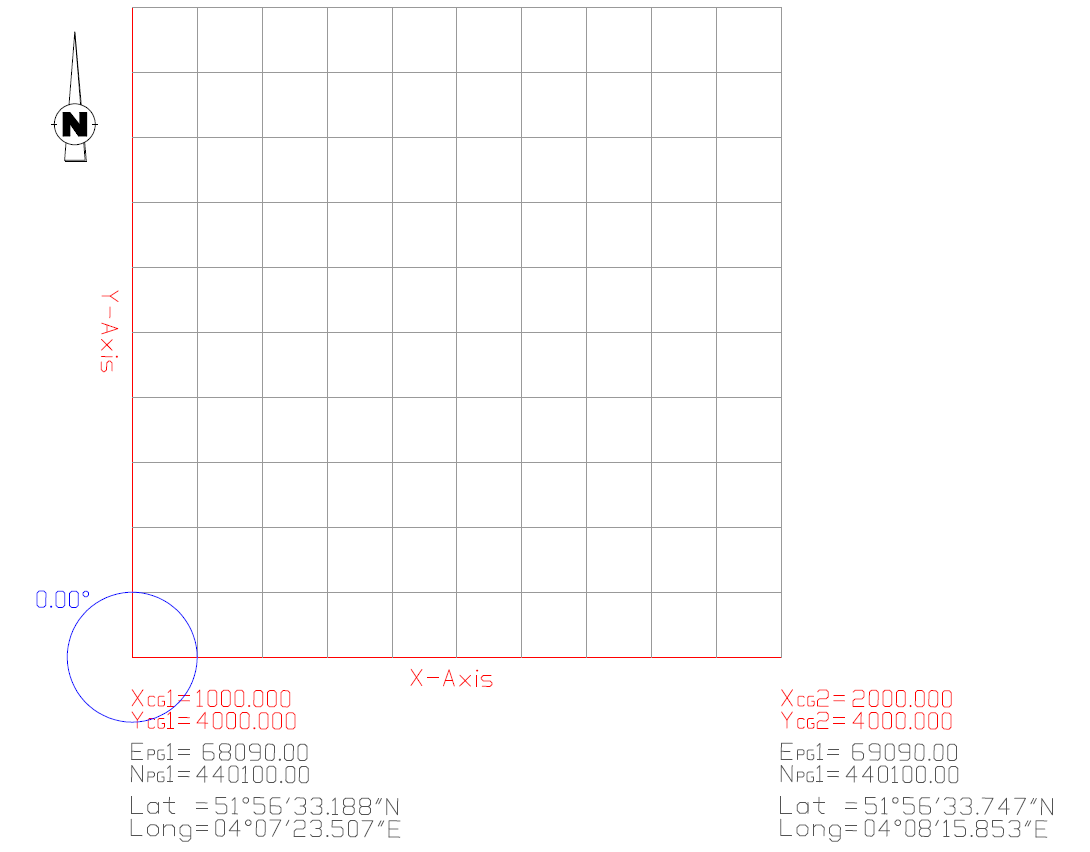
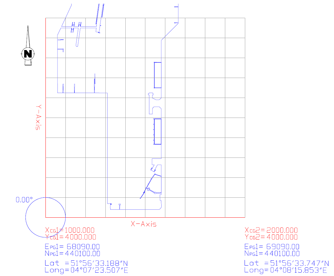
In this example we have 2 coordinates and the azimuth of the Local Grid North direction in the Global Projection Grid (GPG).
The false coordinates of the Local Grid origin have been chosen in such a way that the X coordinate can never be mistaken for a Y coordinate and vice versa (like most common projection coordinates).
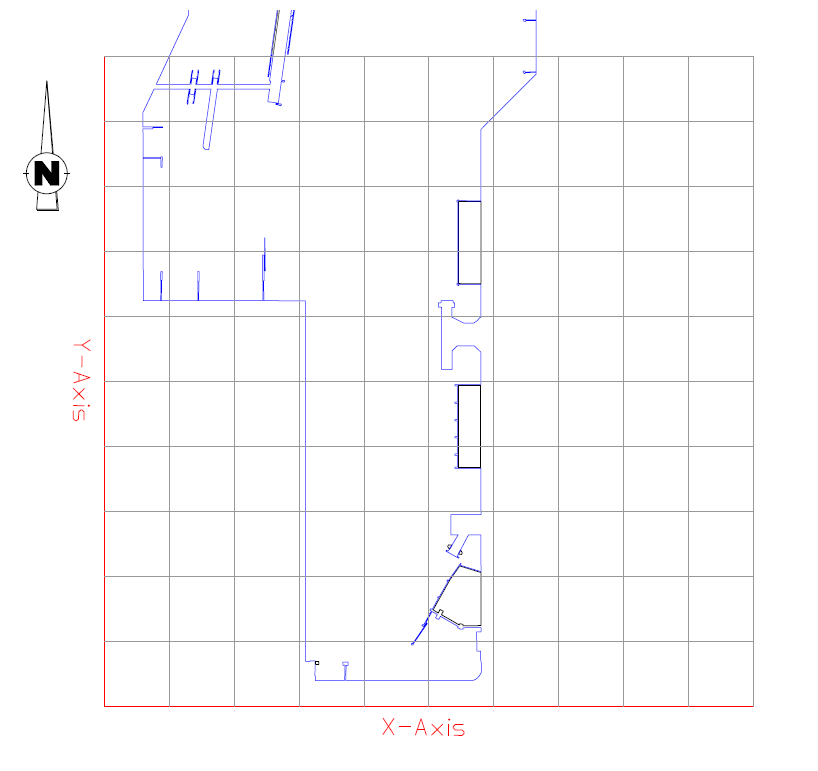
In the picture above we are still using a Predefined Coordinate System and show the created lines (*.QGFLine) and the preferred LCG (*.dxf) as background data.
The red lines show the global projection grid.
A Local Engineering Grid can be defined by:
1. Two Common Points - preferred method
• Coordinates in both LCG and GPG
2. Point and Azimuth
• Coordinates in both LCG and GPG
• Azimuth of the local North direction in the GPG
• Scale factors - which can be difficult to determine
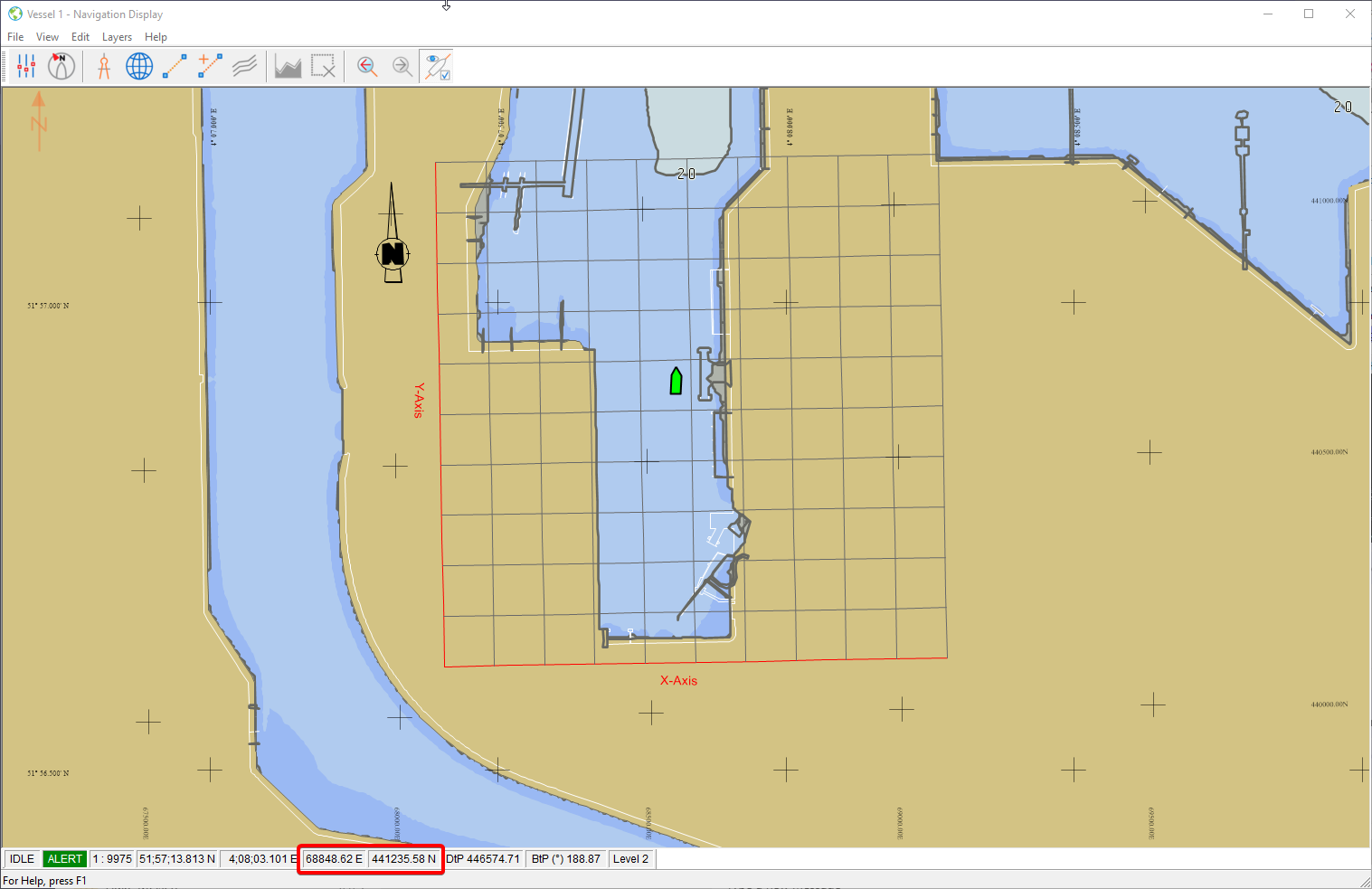
Results in online Navigation Display:
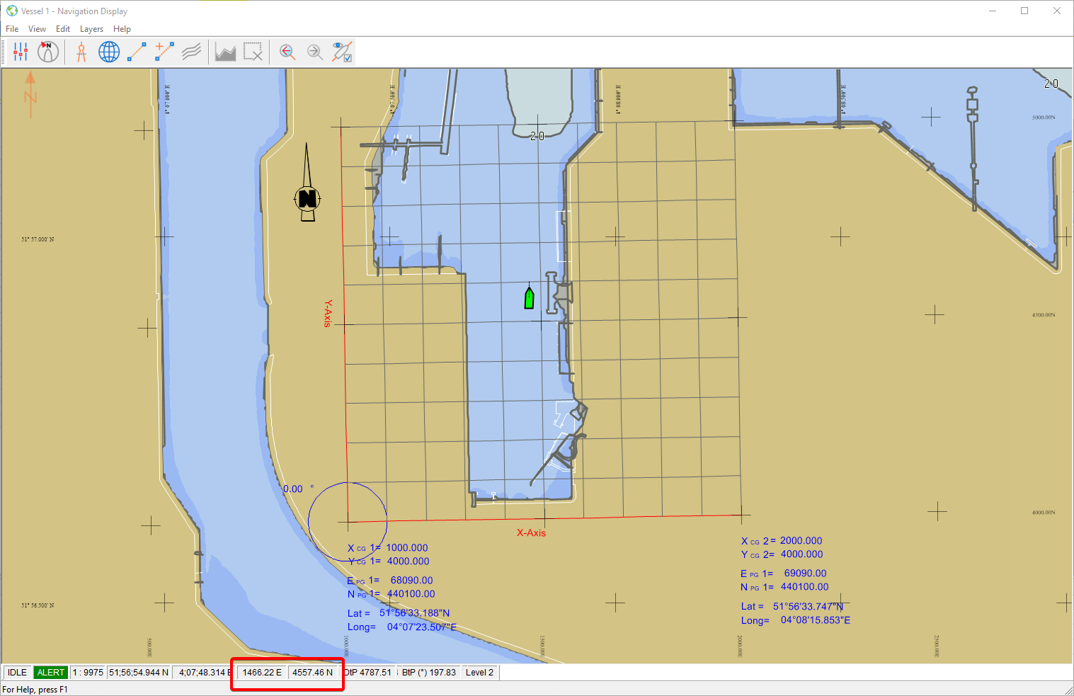
Online in the Navigation Display this will result in the Projection Grid (red lines) being displayed as a Local Engineering Grid and the coordinates all being displayed in Local Engineering Grid coordinates.