
How-to Object Linking
This document describes how object linking works in Qinsy. The object linking functionality in Qinsy is designed to calculate the exact position and attitude of multiple objects that are physically connected with a swivel joint or a hinge.
For example: a crane comprises a cab where the operator sits, a boom that is hinged to the cab, a stick that is hinged to the boom, and a bucket that is attached to the stick via a hinged or swivel joint.
Another example would be the dredge arm on a hopper suction dredger. Here the dredge head is hinged to the lower suction pipe, which in turn is hinged through the swivel to the upper suction pipe and onto the suction connection.
In Qinsy, each of these moving components that make up the whole is termed an object, and the idea is to "link" one object to another or in other words: to establish a relationship between the object pieces making up the whole. There is usually a main object which is fully positioned and oriented, i.e. the main object should have its full position and attitude known. Since the other objects of the whole bear a relationship to the main object, you only need an angular observation on the axis of the joint in order to link one object to another. The observation can be either an absolute or a relative observation.
In this way it is possible to link multiple objects.
To use a hydraulic crane setup as an example:
The main crane object (the Cab) is positioned using a GNSS, a heading device, and a pitch-roll sensor. This means the Cab position and attitude are completely known. The Boom is hinged to the Cab, and can only move up and down. Hence if you know the position and attitude of the Cab, and you know the pitch of the boom (or angle of the boom measured at the hinge), Qinsy can compute the absolute position and attitude of the Boom. The Stick is connected to the end of the Boom. Knowing the pitch of the Stick, or the angle measured between Boom and Stick at the joint, Qinsy can compute the real-world position and attitude of the Stick. Similarly, the absolute position and attitude of the Bucket can be computed because it is linked to the end of the Stick. Boom, Stick and Bucket are linked objects. The observations that establish the relationship of one object linkage to the next can come from an absolute encoder on the hinge, or a pitch sensor on the object. In linking all the objects of a whole, it is possible to mix these observation types.
Setup
Adding a link can be done using the Link option from the File/New menu. Select the Object and Node Position on the first object and the Object and Node Position on the second object. To use the crane example again, you would define a first node on the first object (Cab), at the hinge to the second object (Boom), and you would define a second node at the end of the Boom that affixes to the Cab. The idea is to link the relevant nodes of the two objects.
Once you have defined the link, it will be shown in the tree under the link item listed under the first object. This is akin to creating a parent-child relationship, i.e. the linked object is dependent on the first object.
On the second object an observation needs to be defined. In our example, the second object is the Boom. In case of an absolute measurement the system would be either a Pitch, roll or heading measurement.
In case of a relative angle the system would be a rotation angle sensor. In the setup of the rotation angle sensor, the rotation axis needs to be defined.
For example on a hydraulic crane the observation on the boom can be a pitch observation. Automatically it is defined that the rotation between the crane and the boom is around a hinge that is in the X-axis on the crane around the node that is selected in the link.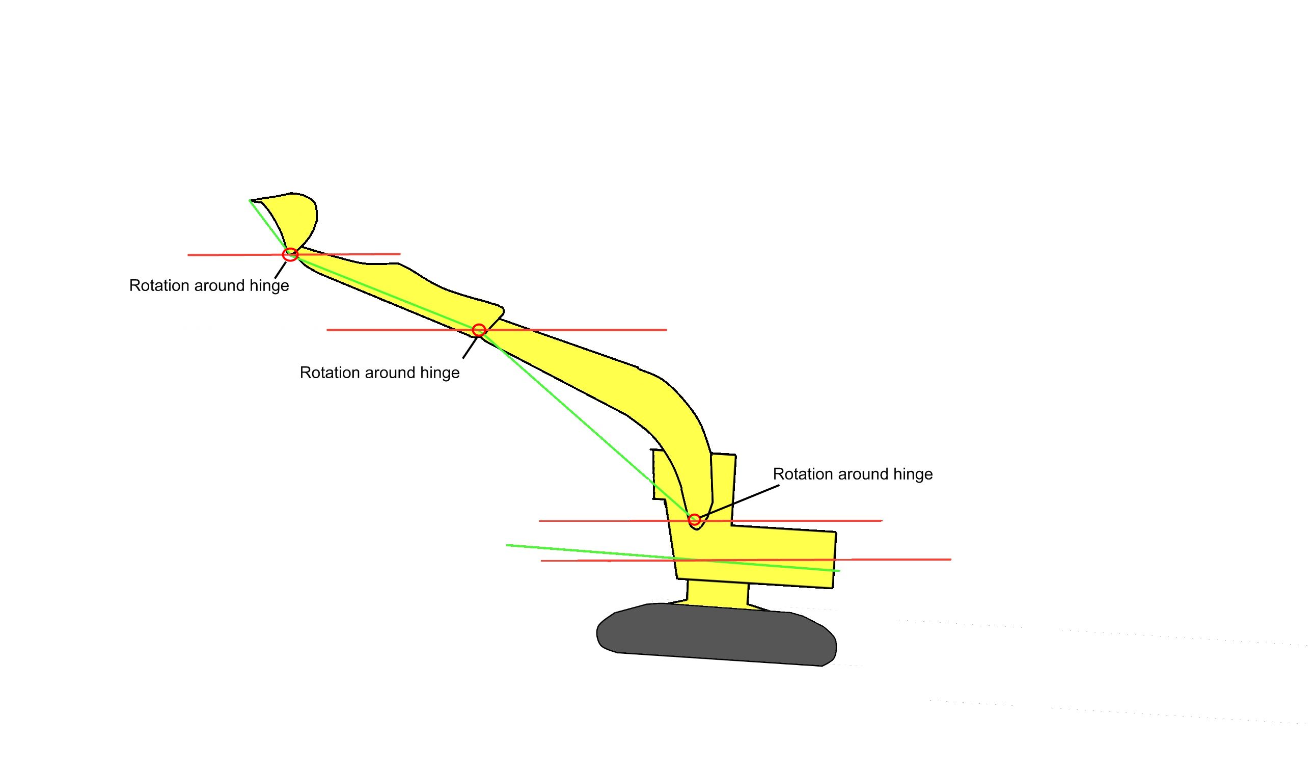
More detailed examples can be found at: