This How-to document describes how to calibrate USBL in Qinsy. Basic USBL theory, the USBL acquisition patterns and the USBL Calibration Utility are described.
The following items are available:
A movie is available on the QPS website which shows how to calibrate a USBL system within Qinsy.
Basic Theory
Definitions
Transducer A transmitter/receiver, often hull-mounted, which sends out an interrogation signal on one frequency and receives a reply on a second frequency, often spaced only 0.5kHz apart. The polar diagram is usually hemispherical or omni-directional. Transponder A receiver/transmitter, installed on the seabed or a submersible (relay), which, on receipt of an interrogation signal (command) on one frequency, sends out a reply signal on a second frequency. The polar diagram is usually hemispherical or omni-directional. The transducer and transponder work in conjunction with each other. Beacon/Pinger A transmitter attached to the seabed or a submersible, which continually transmits a pulse at a particular frequency, i.e. free running. The polar diagram is omni-directional or hemispherical. Hydrophone A directional or omni-directional receiver, hull-mounted, which is capable of receiving a reply from either a transponder or a beacon/pinger. Responder A transmitter, fitted to a submersible or on the seabed, which can be triggered by a hard-wired external control signal (command) to transmit an interrogation signal for receipt by a transducer or hydrophone. The polar diagram is omni-directional or hemispherical. Often used in the hyperbolic mode in acoustically noisy environments.
Introduction
A typical USBL acoustic positioning system requires a surface vessel with a hull-mounted transducer. This comprises an array of hydrophones arranged so that they form two orthogonal planes with at least one hydrophone common to both planes. If a transponder/responder or beacon (pinger) is mounted on the seabed, on a submersible vehicle, or on some underwater structure, the time of arrival of the signals from the transponder/beacon at the various hydrophones of the array will yield the slant ranges/bearings between the two and lead to the calculation of the position of the surface vessel relative to that transponder or beacon.
Ranges are derived from the one- or two-way time of travel of an acoustic signal between transducer and responder/transponder. This requires that the time of signal emission and reception be known.
Bearings may be derived from differences in reception time of an acoustic signal at the orthogonal hydrophones of the transducer array. Differences in reception time are translated into incidence angles, measured between the XZ plane and the acoustic source, and the YZ plane and the acoustic source. Bearings are then derived from incidence angles.
Four modes of computing position are available with USBL systems:
Beacon (pinger) mode requiring depth input and incidence angle.
Transponder mode requiring range (from two way travel time) and incidence angle.
Responder mode requiring range (from one way travel time) and incidence angle.
Transponder/responder mode with depth giving improved accuracy by combining slant range and depth with incidence angle.
More background information can be found in the Knowledge Base document "USBL Theoretics".
Parameters checked in USBL Calibration
The Qinsy USBL calibration program assumes that the center of the transducer array has been installed coinciding with the URP (USBL Reference point), or that corrections for non-coincidence have been accounted for within the USBL sensor itself. X, Y, and Z values output by the USBL sensor are thus referenced to the URP. Given that assumption, the following parameters are checked and corrections computed:
Transducer Offset C-Os: dX, dY and dZ
Non-coincidence of the center of the transducer array and the URP that may be due to mounting errors or measurement errors in determining offsets between the two.
Roll, Pitch and Alignment C-Os: Rx, Ry and Rz
Alignment errors may be due to:
The planes of the transducer hydrophone array may not be exactly parallel with the planes of the vessel URP reference system, leading to errors in determination of incidence angles reduced back to the LRS, and hence in bearings between transducer and transponder/beacon.
The entered gyro C-O may not be exactly correct, introducing error.
Pitch and roll angles measured by the VRU may be in error, either due to misalignment or mis-calibration of the VRU itself.
The value of the Grid Convergence used may be in error.
Scale Factor
The entered value for speed of sound in water may be in error, thereby affecting the computation of range, and hence XYZ coordinates.
USBL acquisition patterns
Acquisition pattern for DP vessels
The most common acquisition pattern for dynamically positioned (DP) vessels is the Four-Quadrant method. The Spin-Check and the Z-Check are checks for the X, Y offsets and the Z offset. While a triangular acquisition pattern is frequently used, it is recommended to perform a Four-Quadrant acquisition if possible. If other patterns are used the USBL Calibration Utility will still calculate calibration values, but these may be less accurate.
Four-Quadrant method
With the Four-Quadrant method measurements are made at four or five different locations relative to the transponder beacon. The following actions must be taken to conduct a good USBL acquisition.
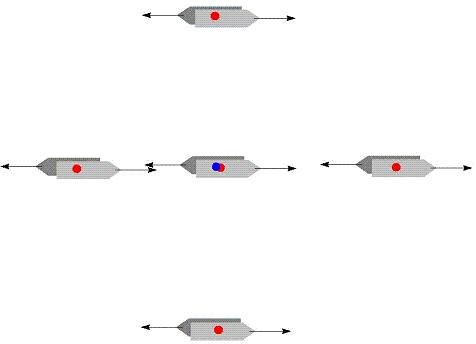
Acquire data at four locations around the beacon and one above the beacon. The fifth position on top of the beacon is not affected by either pitch or roll or by heading misalignment and will give a good check on the consistency of the Z data. If the mean sound velocity is good or if the scale factor is not to be estimated, then this fifth location is not really necessary.
In the figure below the blue dot is the beacon position, the red dots are the USBL transducer positions. Measurements should be made on reciprocal headings at each location.
Make sure that the beacon is observed from the transducer in a direction along or perpendicular to the vessel headings. Either X or Y must be close to zero (for the USBL data relative to the transducer). If the vessel heading needs to be changed due to weather conditions, then the geometry of the four 'quadrant' locations must be rotated with respect to the beacon.
With opposite heading (the arrows represent ship's heading) the total number of measurement sets is 8 or 10.
Apply tidal corrections during the recording otherwise there will be an error in the Z offset, unless an accurate height is defined (e.g. RTK heights).
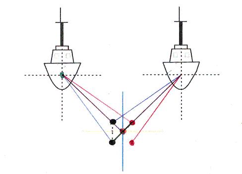
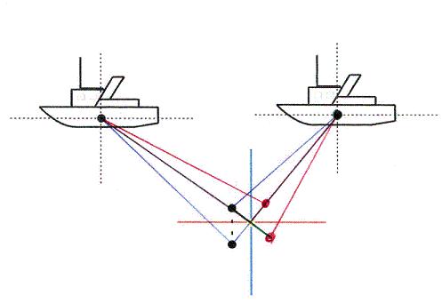
Measure in two opposite headings, this will eliminate roll and pitch errors (see figures below). First complete one round with the same heading and then execute the second round with a reversed heading. If you swap the heading on each point instead of performing two rounds, there is the potential to introduce gyro error as it takes time for the gyro to settle; each heading deviation will influence the results of the calibration.
Roll error: similar error in the starboard direction, equal and opposite errors in down direction.
Horizontal distance to beacon must be half the water depth to a maximum of 500 meters, for example with a water depth of 50 meters the horizontal distance should be 25 meters.
The orientation of the vessel towards the beacon should be perpendicular or in continuation of the heading (see figure below).
Minimise acoustic noise. It is better to drift a little bit and use the thrusters as little as possible instead of using them at full force just to try and stay on the same position.
Spin check
To check whether the calibrated values (scale factor, roll, pitch and heave) are still valid a Spin-Check can be performed. The vessel must be placed above the beacon and a slow 360 degrees rotation must be performed.
An assumption is made that X/Y/Z values output by the USBL system are referenced to the USBL Reference Point (URP). The URP can be the centre of the transducer array, or it can be coincident with any other location on the vessel. The second possibility means that corrections for transducer offset to the URP have already been applied within the USBL system itself. However, it is likely that errors were made in installing the transducer and/or in measuring offsets between transducer and URP.
This calibration option uses surface positioning and USBL fix data from the spin field manoeuvre to calculate C-O values that correct for any errors in achieving coincidence of the USBL transducer and the URP. C-O values, dX and dY, are computed as follows:
Compute the Easting and Northing of the transponder in the absolute reference system for each fix using antenna coordinates calculated from surface navigation as the starting coordinate.
Compute the mean of all the transponder positions.
Compute dE and dN between each individual transponder position and the mean transponder position.
Translate dE and dN values in the absolute reference system to dX and dY values in the local reference system.
Mean all the resulting dX/dY values. These values represent the offsets FROM the URP TO the true location of the USBL transducer, the signs being consistent with the established convention, i.e. Fwd=+ve, Stb=+ve.
Having obtained dX and dY offset values, the choice of how they are to be applied remains. Two solutions are possible:
either: dX and dY values can be added to the offset values measured FROM the vessel reference point TO the URP. In effect this creates a new URP coincident with the vessel reference point. X/Y/Z values can then be converted to absolute coordinates and applied to the absolute coordinates of the vessel reference point to yield absolute coordinates for the transponder location.
or: dX and dY values can be interpreted as C-O values to be applied to the X/Y/Z values output by the USBL. Since both C-O values and USBL X/Y/Z measurements are made in the vessel local reference system, signs of C-Os remain the same irrespective of vessel heading.
Z-check
Whilst sitting above the transponder the vessel echosounder depth and the USBL Z reading should be observed simultaneously. This option compares only "Z" values read out of the USBL and depth readings from the echosounder to check the transducer offset from the vessel reference point in the Z-axis. The assumption is made that the echosounder readings are correct values for depth. The USBL "Z" values are measured between the transducer and the receiver/transmitter element in the transponder. Depth values obtained from the echosounder record the vertical separation from either transducer to seabed, or sea surface to seabed, depending upon whether the reference plane set in the echosounder is the transducer or sea surface. The plane for depth reference used in the calibration program is the URP (USBL Reference Point). Therefore echosounder values that refer to sea surface must first be corrected for the draft of the transducer to yield "computed" depth values measured between echosounder transducer and seabed, and secondly, these values can then be referenced to the URP by entering the offset distance FROM the URP TO the echosounder transducer (+=Down).
One other correction needs to be made. Since USBL depth measurements are made between URP and the receiver/transmitter element of the transponder, and corrected echosounder values are given for the vertical separation from the vessel reference to seabed, a correction for the vertical separation FROM the transponder TO the seabed must be made. This distance is always positive (+=Down). In this way, echosounder measured depths and USBL measured depths can be compared directly.
Acquisition pattern for non-DP vessels
If the vessel is not fitted with a DP system, it is almost impossible to hold the vessel statically in place whilst observations are being made. Therefore the vessel must be sailed around or across the transponder in a predefined pattern to ensure balanced USBL data is obtained. The type of pattern sailed varies according to the type of the transducer head. To ensure that effect of time difference between surface navigation data and USBL data are kept to a minimum the vessel should be sailed slowly along its predefined course.
The two patterns described below are known to be in use. However it is unknown what the accuracy of the results will be.
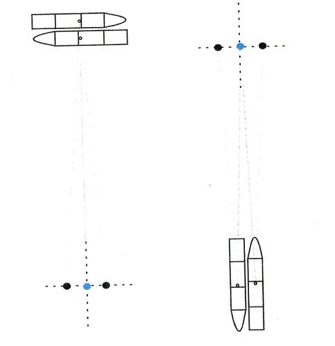
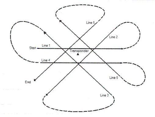
Fixed aft looking transducer head
The pattern shown in the figure below is centred on the position of the seabed USBL transponder.
Data is gathered while the vessel is slowly steaming away from the transponder, this is shown as a solid line in the figure. Data gathering should start when the vessel has passed over the transponder and steady acoustic updates are being received.
Data collection should continue until the vessel has reached a distance equivalent to 3 or 4 times the water depth or until the acoustic readings are seen to becoming erratic, whichever is the sooner.
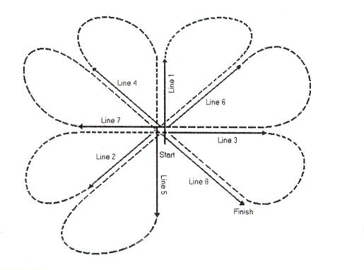
Omni or tracking transducer head
The pattern is centred on the position of the seabed USBL transponder (see figure below). The point of closest approach of all the lines is to be approximately equivalent to the water depth. The lines start and end approximately 3 to 4 times the water depth away from the transponder.
The pattern provides an even balance between lines where the transponder is to port or starboard of the vessel. This will result in observation from the vessel to the transponder in all quadrants being observed
USBL Calibration Utility
After the USBL data is recorded, the USBL Calibration Utility is used to calculate calibration values.
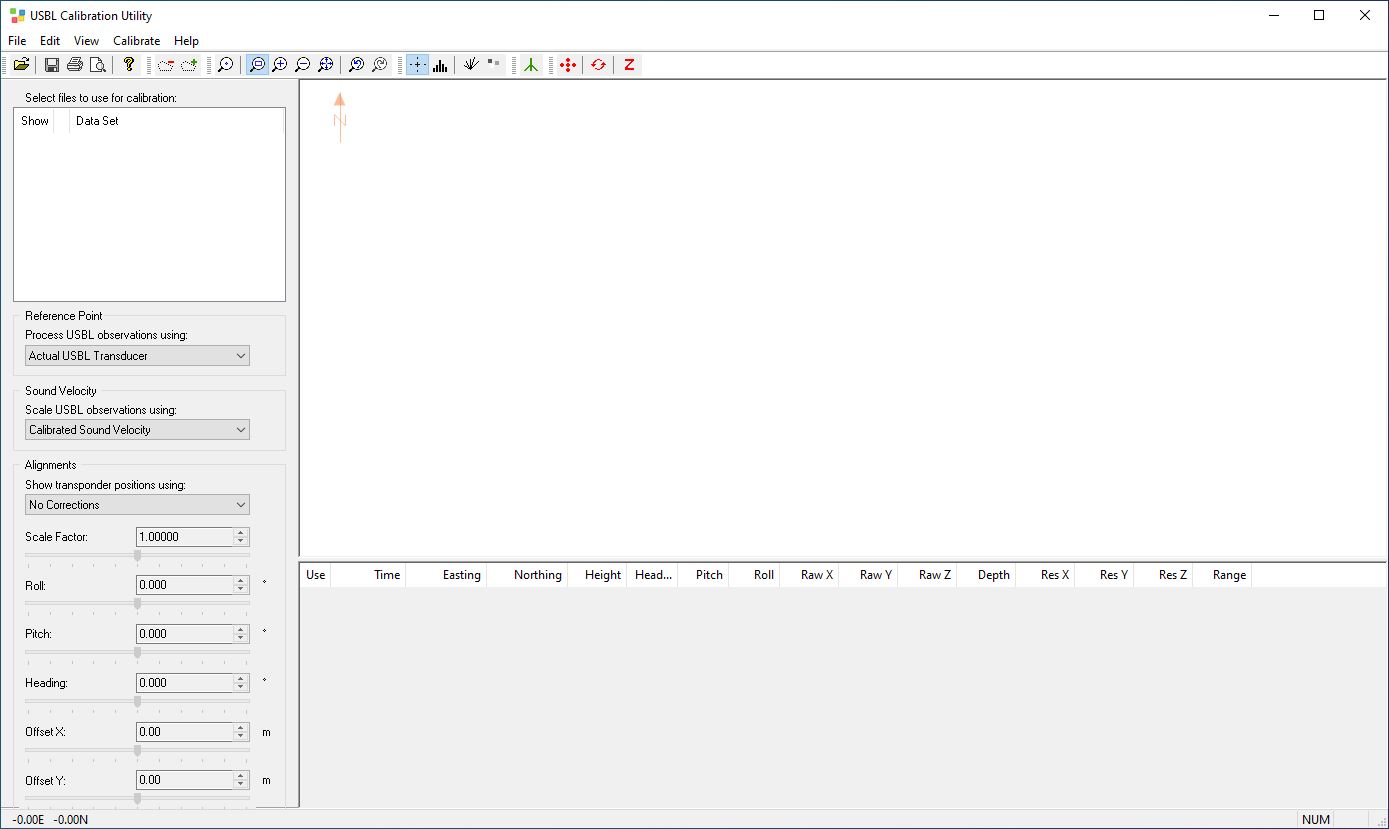
The USBL Calibration Utility is a standalone program in the list of additional QPS programs. The program is started from the Console bottom pane. Use the right mouse button and activate the option for USBL Calibration.
The window consists of four parts:
Top left pane is 'Dataset collection'.
Bottom left pane is 'Alignments'.
Top right pane is 'Geographical display'.
Bottom right pane is 'Numeric display'
The Geographical display is an overview of the transponder positions. The green error ellipse is calculated from these points. The calibration report contains the properties of this ellipse in the part for USBL transponder positions where semi-major axis, semi-minor axis and azimuth major axis is shown.
Steps to perform a USBL calibration:
Select Open from the File menu. Open the recorded databases, select the appropriate USBL settings and select the appropriate sensor for each type of system.
Use the De-select Observation option from the Edit menu to de-select outliers or use the button. Draw a polygon around the datapoints to be removed from the calculations for final results. This data will no longer affect the calibration.
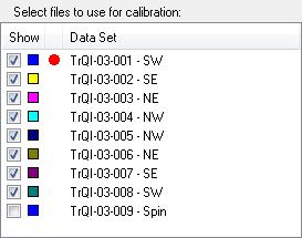
Click on the Show color button to show the databases in different colors.
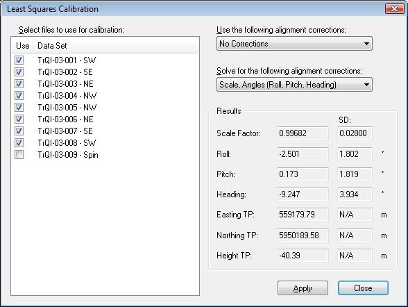
Least Squares Calibration
Make sure that only the lines are enabled that are used for the Least Squares Calibration. This can be done in the top left pane.
To calibrate Roll, Pitch and Heading select the Least Squares calibration option from the Calibrations menu or use the button.
Select No Corrections at "Use the following alignment corrections".
Select what you would like to solve at "Solve for the following alignment corrections"
The values will automatically be calculated. Click on the Apply button to apply the found values to the selected databases and click on Close.
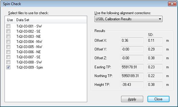
Spincheck
Make sure that only the lines are enabled that are used for the Spincheck. This can be done in the top left pane.
To check the mounting offsets of the transducer select the Spin Check option from the Calibrations menu or use the button.
To be able to perform this check the Roll, pitch and heading errors should be known. So select USBL Calibration Results at "Use the following alignment corrections".
The values will automatically be calculated. Click on the Apply button to apply the found values to the selected databases and click on Close.
Info
Depending on the size of the offset error a decision can be made whether or not to repeat the LSA calibration.
Z-check
The Z-Check is used to check the Z offset of the USBL transducer on the vessel. This option compares only Z values read out of the USBL and depth readings from the echosounder. It is recommended to use the same data that is acquired with the Spin Check manoeuvre.
Make sure that only the lines are enabled that are used for the Z-check. This can be done in the top left pane.
To check the Z-offset select the Z-Check option from the Calibrate menu or use the button.
Select USBL Calibration Results at "Use the following alignment corrections" and enter a Transponder Height.
The values will automatically be calculated. Click on the Apply button to apply the found values to the selected databases and click on Close.
Info
Make sure that tide is applied if no accurate height is defined.
Info
This calibration will only give a good result when the echosounder is calibrated and the correct speed of sound is entered in the echosounder.
Use the Transfer to database option from the Edit menu to transfer the found values for roll, pitch and heading to other databases. Especially the template database. This could also be done manually in the database setup.
For each different calibration a calibration report can be generated by selecting “View” on the menu bar and then “Show Report”.
The roll, pitch and heading correction must be entered in the Database Setup to be effective. To check whether the corrections are applied correctly, the databases can be replayed with the corrections entered in the databases. When the USBL Calibration Utility is started select the “Qinsy database settings” in the Alignments pane. This should give the same result as when USBL corrections are applied.
JavaScript errors detected
Please note, these errors can depend on your browser setup.
If this problem persists, please contact our support.