How-to Static Horizontal Shift Tool
This How-to is a step-by-step description for using the Horizontal Shift Tool on the Dynamic Surface, available from Qimera 2.3 and up.
On this page:
Introduction
The Static Horizontal Shift Tool allows a user to align a Dynamic Surface from a survey to another reference surface that could be either a Dynamic or Static Surface. The user does this by selecting a number of corresponding matching point pairs on each surface, which are referred to as reference points. Qimera will then compute an average XY offset between all reference pairs that can then be applied to the raw sonar files of the Dynamic Surface the user desires to shift. Typically, the user picks corresponding features on the seabed or corresponding features of line objects such as contours to use as reference points. The user can pan or zoom around either surface view and the same corresponding geographic location will be at the center of the view when the views are "locked".
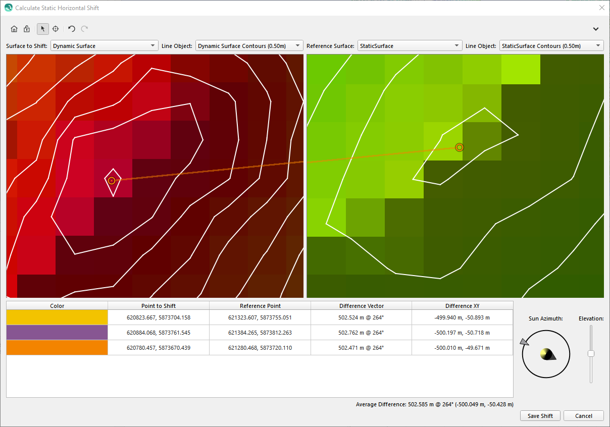
The average XY offset is computed by averaging the XY displacement of all reference pairs in the Point Table. As you register reference pairs by clicking on like features in each window, circular icons appear that represent the location of each pick. The color of the icon helps you see which pairs go together. Each icon also has a "tail" that extends to the corresponding Reference position in the opposite surface view. You can start a pick pair in either surface view. The panels below show how the icons appear as you start and finish your pick on a feature. In this example, the user chose a simple bump that appeared in both surfaces. As you pick, the points are also added to the Point Table.
Step-by-step-guide
Step 1 - Assess & Import your data
In order to use the tool, two surfaces are required. The first surface will function as a reference surface while the second selected dynamic surface will be shifted based on the calculated fiducial points.
Use the profile and/or measure tool to get a rough assessment of the horizontal shift required.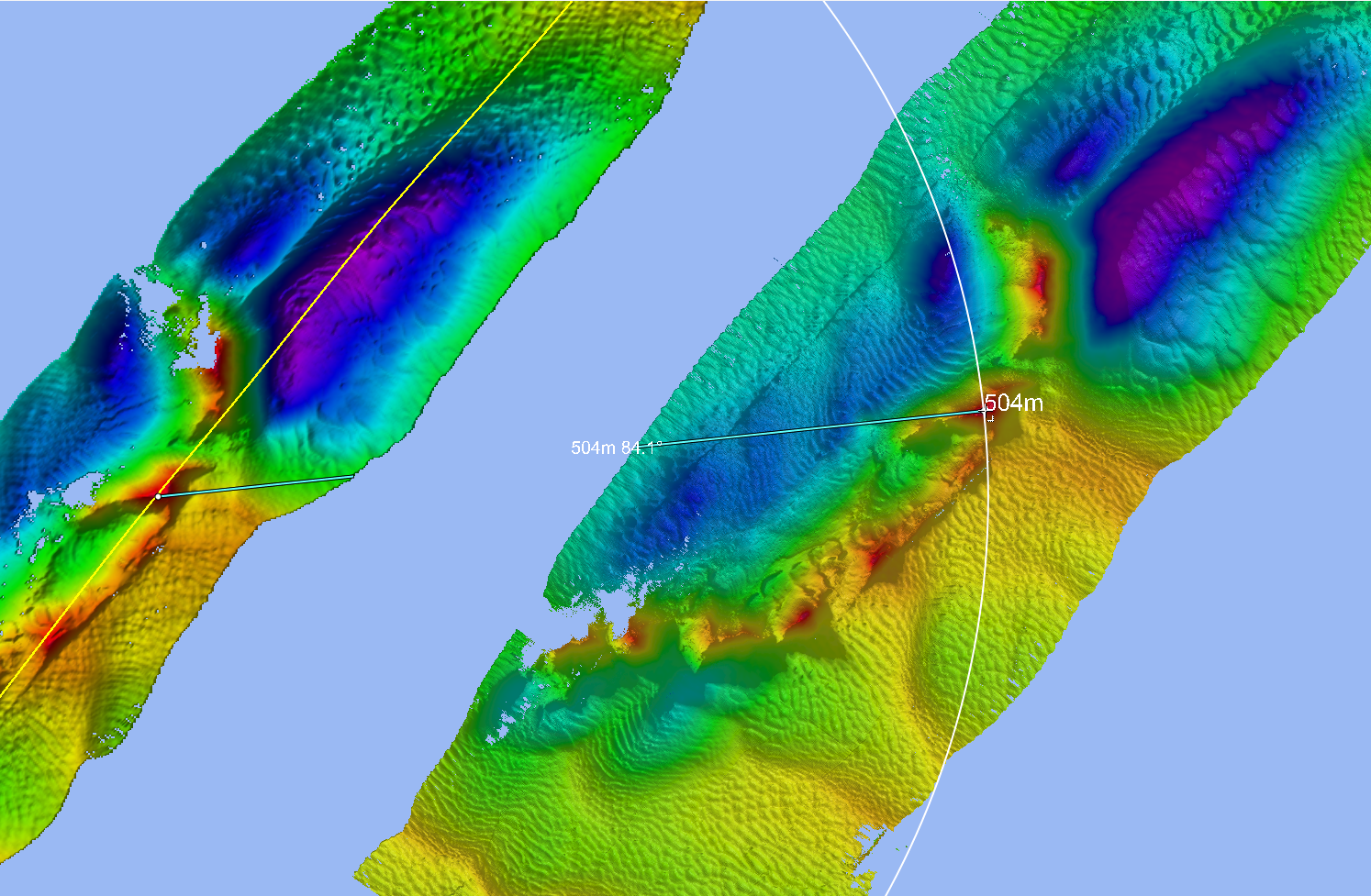
Use the contouring option to create contours, this makes it easier to distinguish features and elevations to use it as fiducial points.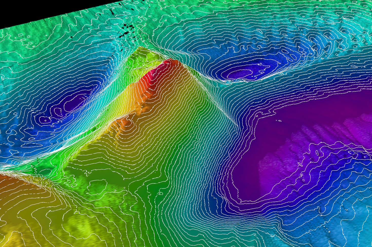
Step 2 - Start the Static Horizontal Shift Tool
Start the tool by going to the tools menu Dynamic Shift > Static Horizontal Shift Tool.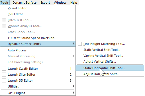
The tool will open. The tool selects the current dynamic surface as Surface to shift. When multiple dynamic surfaces are available, the surface to shift can be changed. 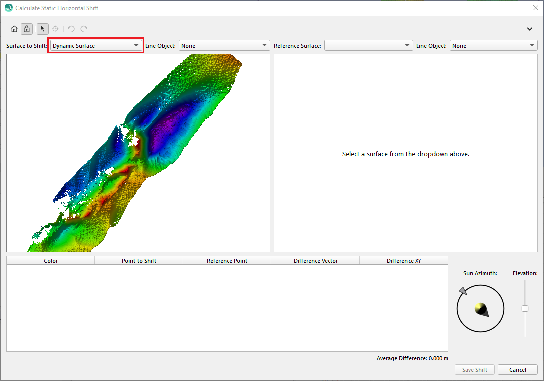
Step 3 - Select Reference surface, Line object & Shading
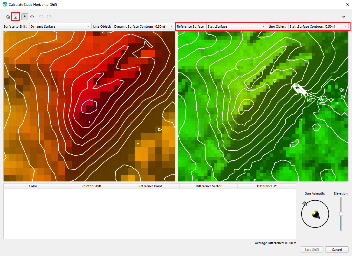
Use the reference surface drop down menu to select the surface you would like to shift towards to. This can be another dynamic surface or a static surface. If available, select the contours as line object. Having contours in the view panel makes it easier to link the same object.
Once the reference surface is selected you can zoom in and out on the surface. Note that the views are synchronized, so scale, zooming level and view point are equal.
When objects surface are far apart disable the view synchronization via the lock icon 
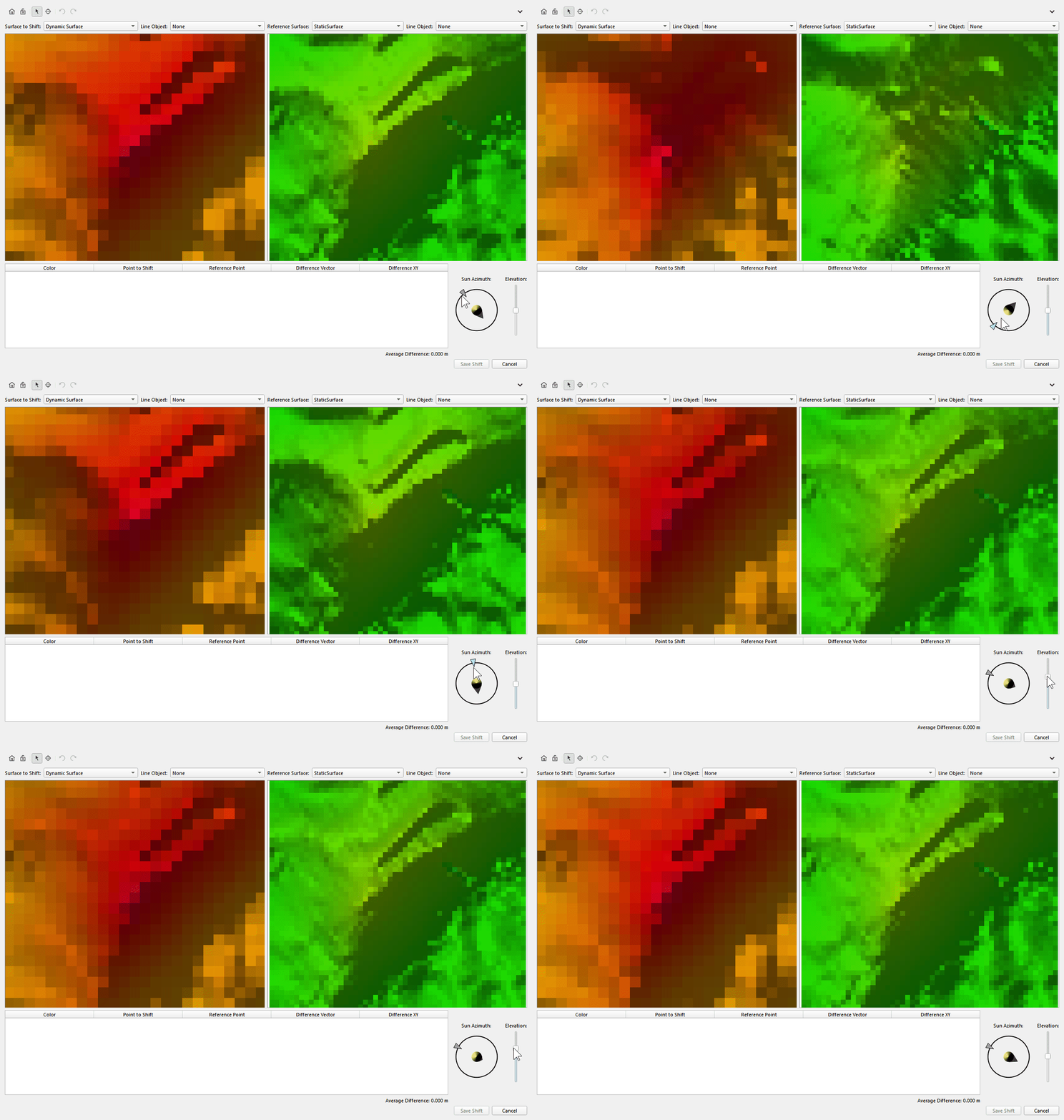
The shading can be adjusted and can help to distinguish particular features to use it as a reference point. Change the azimuth and elevation in the panel.
Step 4 - Select Fiducial points
To select fiducial points go into pick mode by selecting the pick icon 
Repeat the steps to add multiple fiducial points, this will increase the likeliness of the shift. Once finished select Save shift.
A dialog will appear, acknowledge it to apply the shift to the listed databases
Step 4 - Assess results
After applying the results the profile display can indicate if the surfaces do overlap. The shift can be viewed in the processing settings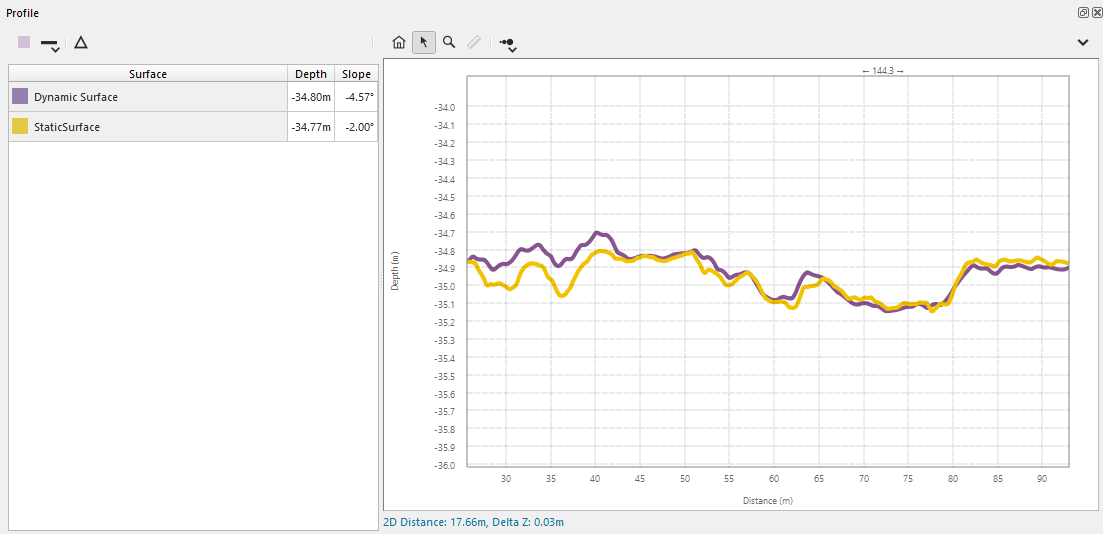
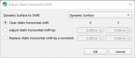
If necessary the shift can be cleared or altered using the Adjust horizontal shift tool.