This How-to document describes how to perform a patch test in Qimera. The document applies to single-head multibeam echosunders as well as dual-head multibeam echosounders.
On this page:
For information on multibeam Patch Test (calibration) theory, please see this Qinsy document: How-to Calibrate a Multibeam Echosounder (Patch Test). This document also describes the sailing pattern for gaining the best patch test results, for both single-head and dual-head multibeam echosunders.
For a more in-depth explanation of the specific functions in the Patch Test tool, please visit our reference manual here: Qimera Patch Test
Warning
Qimera Patch Test Tool has been designed for calibrating both single-head and dual-head multibeam systems. The directions on this page assume you are using a single head multibeam system. There is a section on the calibration of a dual head system at the bottom of this Qinsy document: How-to Calibrate a Multibeam Echosounder (Patch Test). There is also information here: Kongsberg EM2040 Dual Head Calibration
Info
From the Qimera FAQ:
When I apply Patch Test results, the angular offsets are not entered the same for the Tx and Rx transducers in the Vessel Editor, why?
Qimera separates the two transducers in its vessel offsets. The Patch Test Tool will apply the offset corrections to the transducer at which they will have an effect. Roll to Rx, Pitch and Heading to Tx. The values from the Patch Test can also be applied to the motion sensor data instead of the mounting offsets of the transducers.
Patch Test Overview
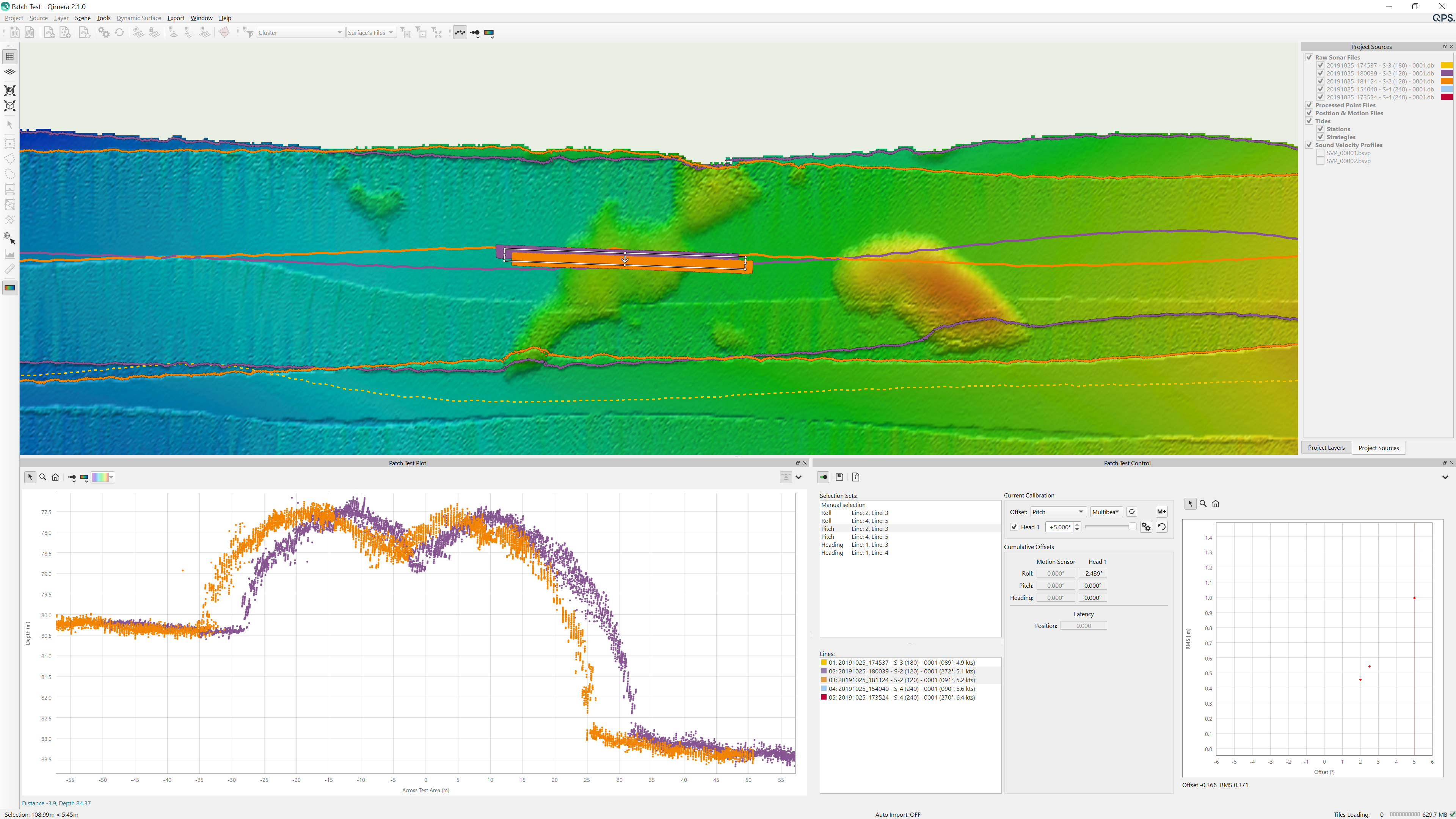
The Patch Test Tool window consists of two hot dockable windows, which are the Patch Test Control Window and the Patch Test plot window. The Patch test tool can be launched by using a hotkey, which can be configured by the user.
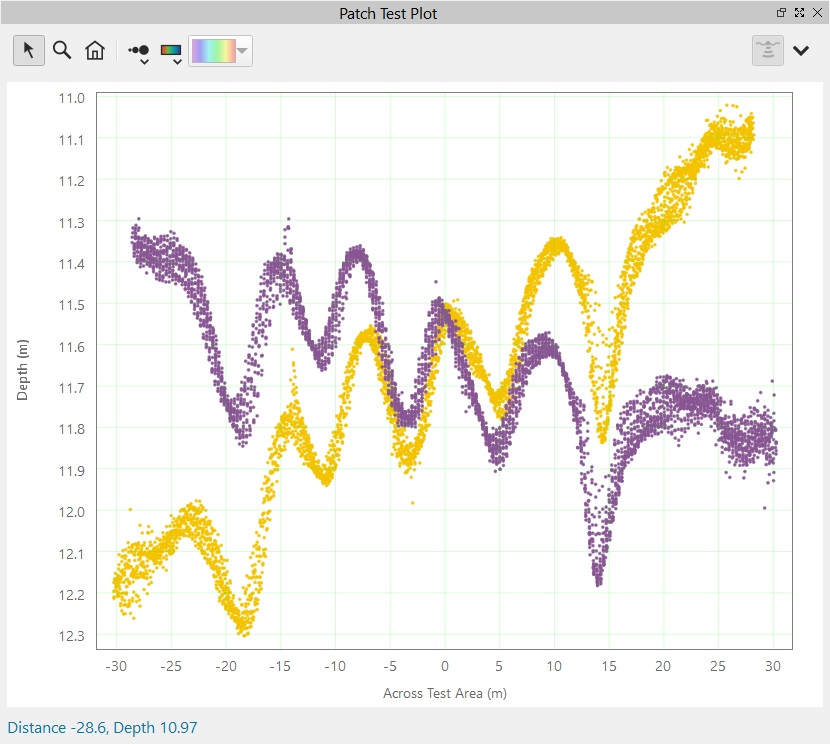
The Patch Test Plot window contains tool buttons and a point cloud cross section displaying the soundings that are within the selection box.
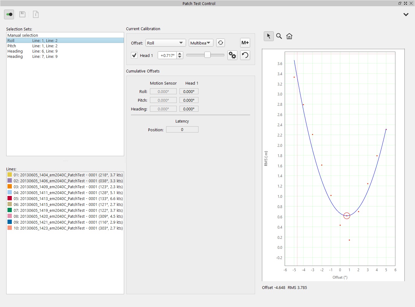
The Patch Test Control window (on the left) has 3 main areas: the Selection Sets (based on the lines listed below), the Calibration area and the Graphical representation.
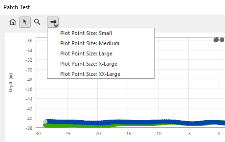
The size of the dots in the point cloud graph can be adjusted using the Plot Size button by using either the drop down menu, or the toggle functionality. Points which have the rejected status can be turned off by using keyboard combo Ctrl+R.
An options drop down tab allows you to select what types of points to view, and gives the options of showing in 3D view, showing the grid lines, and applying multibeam offsets to both TX and RX. Additionally there are options to save the patch plot and the RMS plot to images.
For a more in depth explanation of the specific functions in the Patch Test tool, please visit our reference manual here: Qimera Patch Test
Step-by-step guide
Step 1 - Setting up the data and activating the patch test tool
Ensure you have loaded Raw Sonar Files into your project. These can be added using the 'Source' pull-down menu at the top of the main window.
It's best to build a dynamic surface. Select one or more of the sonar files from within the Project Sources window. This window can be toggled in the 'Window' pull-down menu. Choose the same lines that will be used in the patch test. Select 'Create Dynamic Surface' from the 'Dynamic Surface' pull-down menu or click the 'Create Dynamic Surface' Icon.
Select the lines to be loaded into the patch test tool from within the Project Sources window. Choose all the relevant lines to test for roll, pitch, heading, and latency.
Click on 'Patch Test' in the 'Tools' pull-down menu at the top of the Qimera Window. This will bring up the Patch Test window with your selected lines loaded.
Step 2 - Selecting lines and determining offsets
Roll Offset
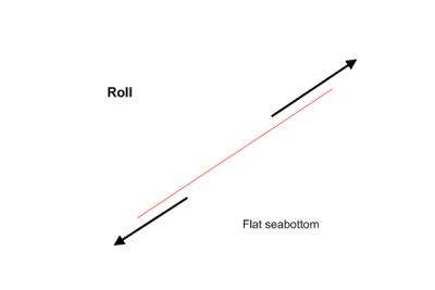
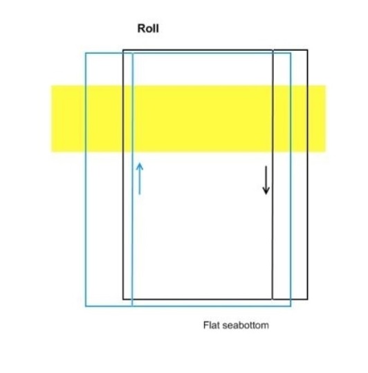
The roll test uses two lines of data, run in opposite directions with the same vessel speed over the same ground (need to overlap as much as possible). An area of flat seabed is best for this test. From Howto Calibrate a Multibeam Echosounder . The first graph shown below shows a line pair suitable for the roll calibration of a single-head multibeam echosounder . The second graph shows a line pair that is suitable for a roll calibration of a dual-head system
With the patch test tool open and relevant lines loaded, click on the pre-selected pair of lines in the line selection box. Alternatively, select your own lines. The pre-selection is done based on the auto-pairing algorithm.
Adjust the location of the selection box in the geographic window. It should be oriented at 90 degrees to the lines.
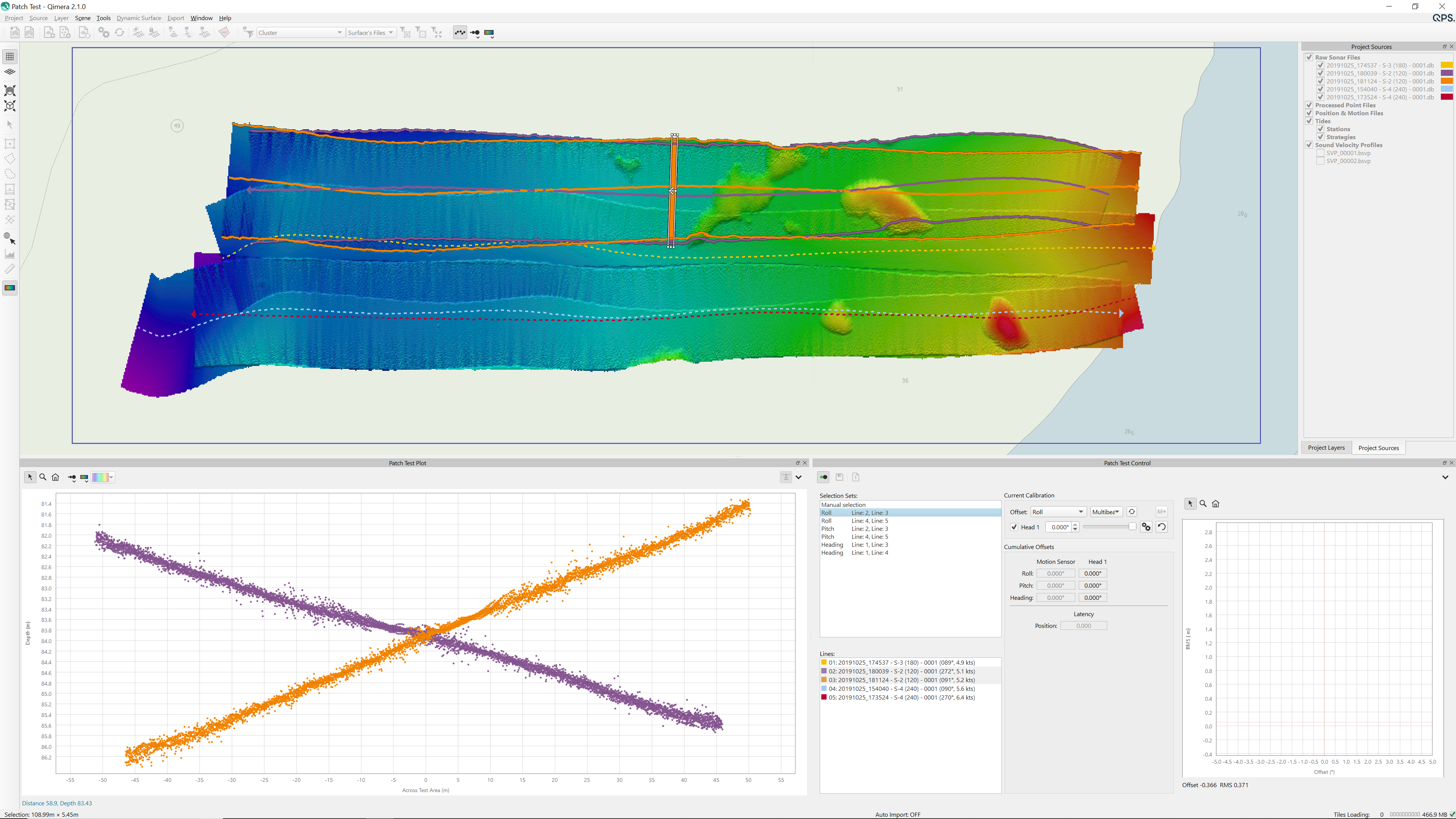
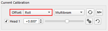
Ensure that 'Roll' is selected in motion pull-down menu box.
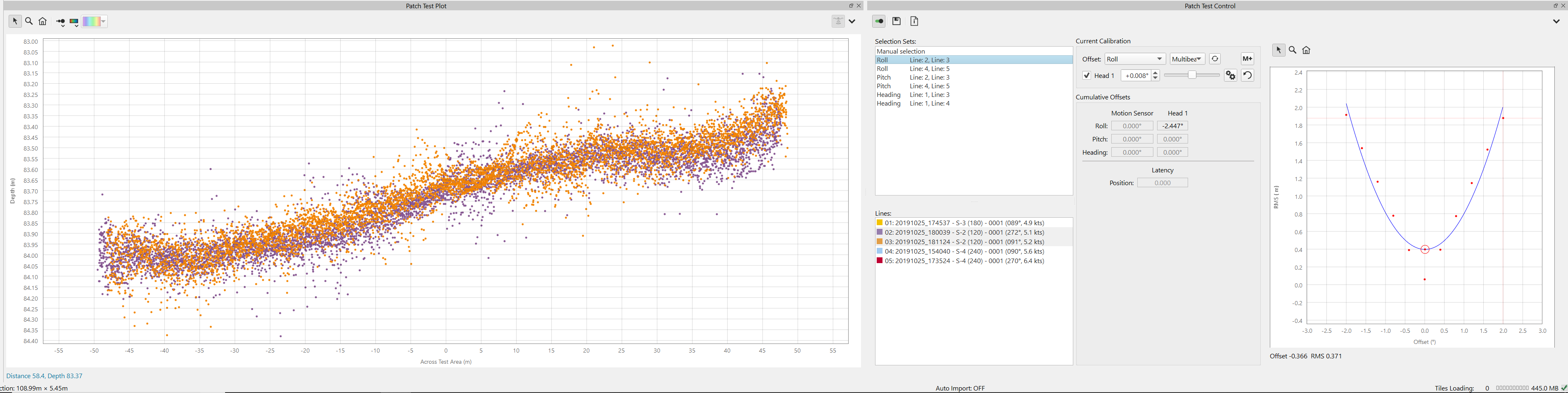
Now you can determine the offset manually by dragging the slider, or automatically by using the Auto Solve button The two sounding cross sections should be aligned as closely possible. In order to enable the Auto Solve for a dual-head system, you will need to disable one of the two heads, both heads should be calibrated separately.
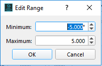
If the angular change is too coarse, adjust the scale using the 'Edit Range' button at the right end of the slider. In this case, the Starting and Ending Values can be changed to something like -1 and 1
Info
It may be necessary to increase or decrease the width of the selection box in the geographical window. A very narrow box will decrease the number of points that are in the cross sections. This may be necessary in areas where the seabed is not as flat as it could be. The selection box can be resized, rotated, or redrawn at any time.
If you are using the auto-solve check that the parabola makes sense before applying. Once the cross sections are matched, the offset value needs to be saved. Do this by clicking the 'Add Calibration' button
Pitch Offset
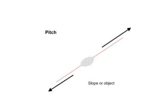
To be able to determine the C-O for pitch, the patch test uses two lines of data in opposite directions with the same vessel speed over the ground. A seabed with defined targets or is sloped (along track) is best for this test. From How-to Calibrate a Multibeam Echosounder. The first graph shown below shows a line pair suitable for the pitch calibration of a single-head multibeam echosounder . The second graph shows a line pair that is suitable for a pitch calibration of a dual-head system.
The patch test for determining the pitch offset, is conducted much the same as the roll test above, with 2 critical differences:
The selection box in the geographic window must be aligned to be parallel the the direction of travel and placed on top of the centre.
Move the box to a slope or object on the seafloor.
Pitch must be selected in the motion pull-down menu or select pitch in the selection sets:
From here, follow steps 4-6 in the Roll Offset section to conduct a pitch calibration and add it to the MBES offsets.
Heading Offset
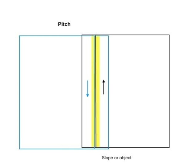
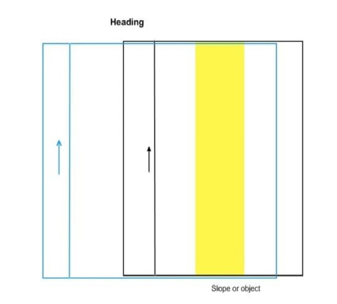
The heading test uses two parallel lines of data that were run in the same direction with the same vessel speed. These lines are spaced apart by about half a swath width or a little less. There must be an area with slope (along track) or a defined target in the area of overlap. From How-to Calibrate a Multibeam Echosounder. The first graph shown below shows a line pair suitable for the heading calibration of a single-head multibeam echosounder . The second graph shows a line pair that is suitable for a heading calibration of a dual-head system.
The patch test for determining the heading offset is conducted much the same as the roll test above, with 2 critical differences:
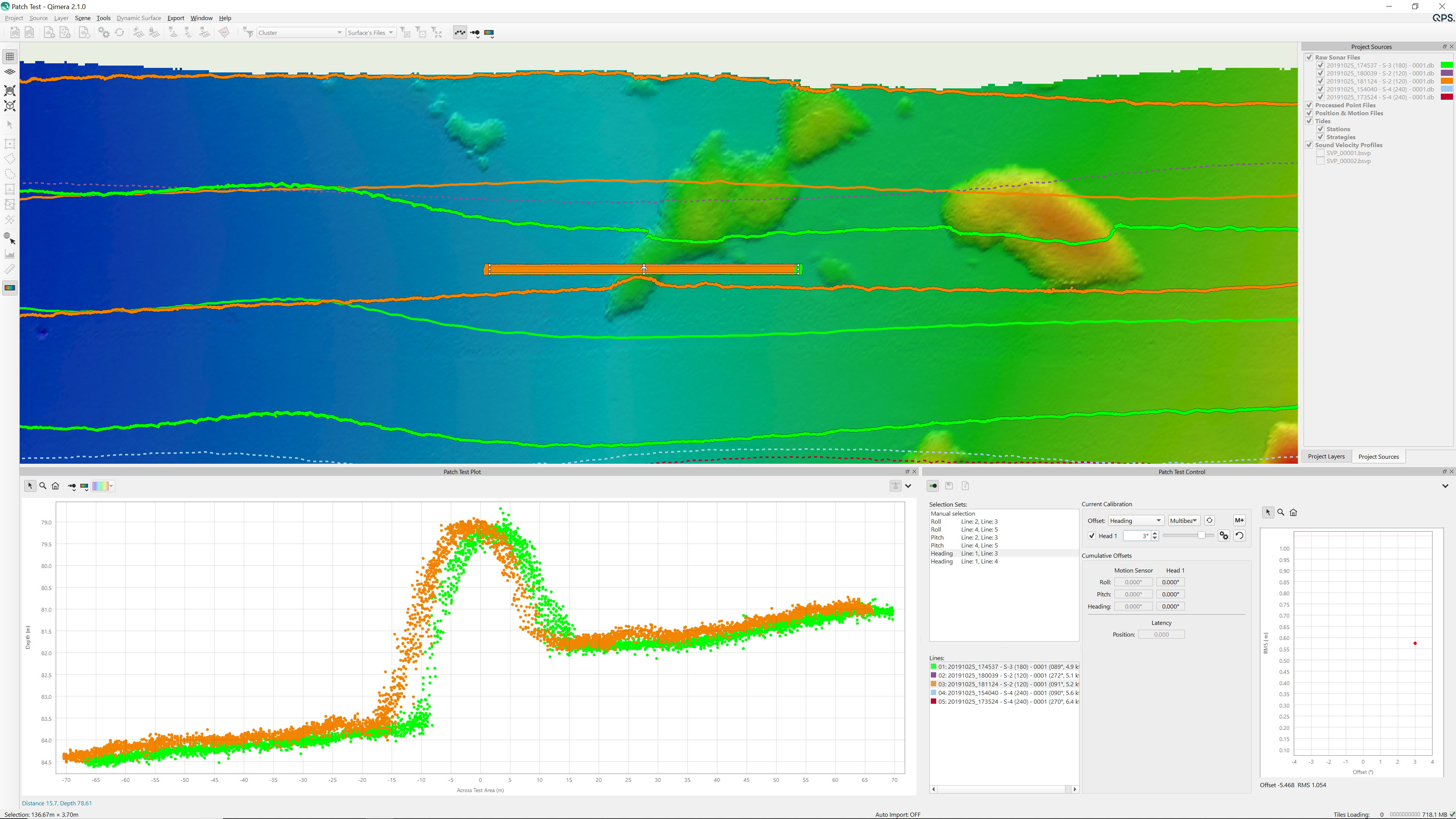
The selection box is oriented parallel to the lines, between them, in the area of overlap. There should be a discernible slope or target within the box. In the following graphic, the two lines being used are highlighted in green and orange The selection box is positioned between them in the outer beams.
Heading must be selected in the motion pull-down menu, or select heading in the selection sets:
From here, follow steps 4-6 in the Roll Offset section to conduct a heading calibration and add it to the MBES offsets.
Position Latency
The position latency calibration tool uses two lines of data, run in the same direction with different vessel speeds over the same ground (overlapping as much as possible). There must be an area of slope (along track) or a defined object below the vessel.
Info
The larger the difference in speed between the two lines, the more evident the position latency will be. It is also beneficial if the data is collected in an area that is reasonably shallow, this will increase the resolution of the slope or targets.
The latency test is conducted much the same as the roll test above, with 2 critical differences:
The selection box in the geographic window must be aligned to be parallel the the direction of travel and placed on top of the center of the lines.
Position Latency must be selected in the motion pull-down menu.
Step 3 - Applying patch test offsets
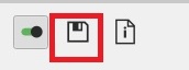
Once you have finished the patch test click Save and Apply in the Patch Test window.
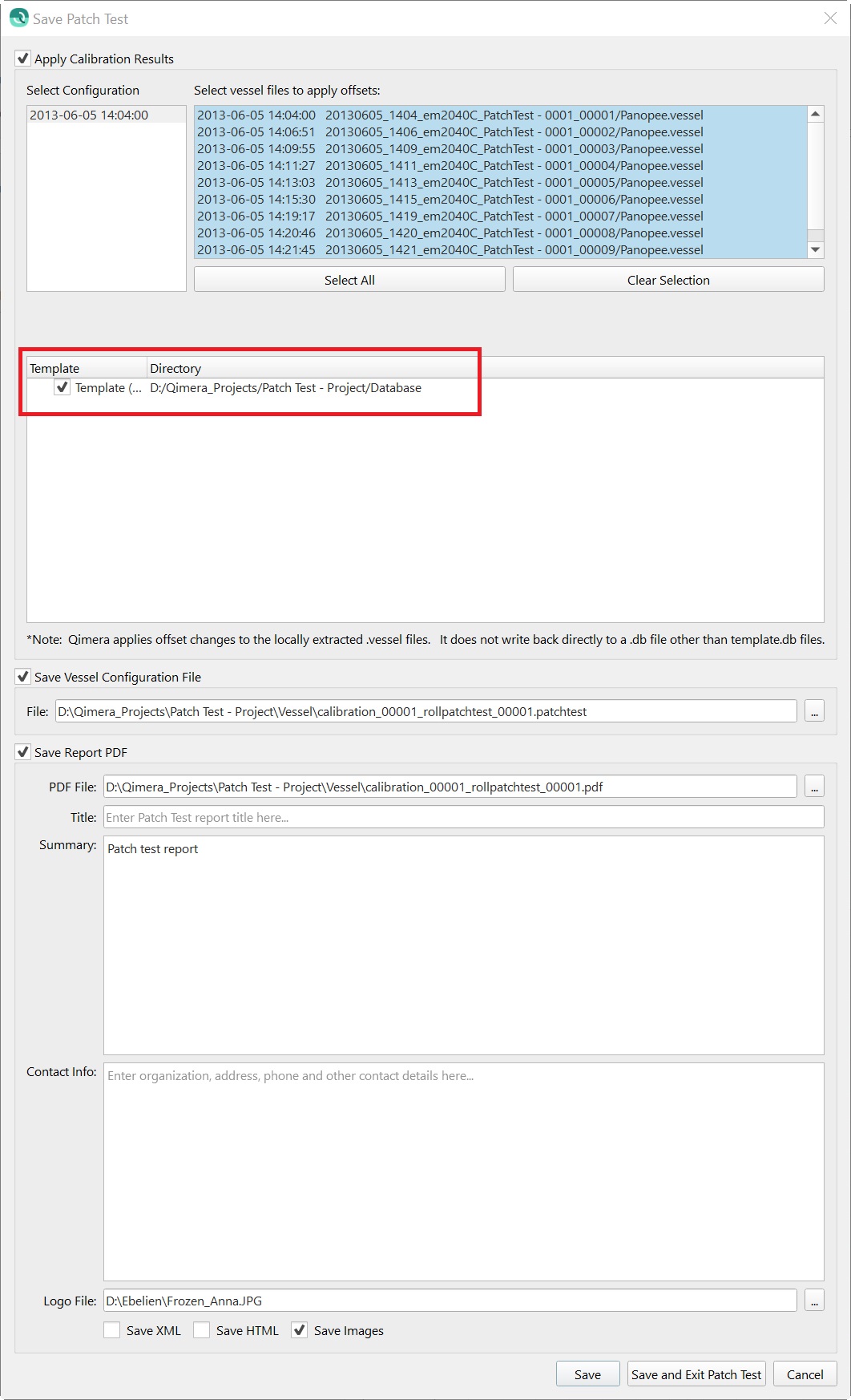
Give the patch test a title and click Save.
You are then given the option which configuration (if you have multiple ones) and which lines you would like to apply the patch test values to.
Click OK to apply the configuration to your lines. They will then need re-processing. In this GUI you will also need to define the settings for the Patch test Report. Apply patch test C-O values to the Qinsy *.db file in case you will need to update the template for data collection, this is highly recommended: the check box to apply C-O to template db file is checked by default.
Once complete you will find the Patch Test report, with images of the areas used in the Vessel folder of your project.
For completeness: you may want to check if C-O values have made it to the vessel configuration, by checking the vessel config for the appropriate lines in Qimera.
Warning
For Qinsy users, who are not using Qimera for processing: it is recommended to double check whether C-O values have made it to Qinsy template Database Setup, before data collection. Please note C-O values will not be applied to the recorded Qinsy db files. In case you will need C-O values applied to recorded Qinsy db files after the fact, you will have to clone the C-O values from template db files to recorded db files and then Replay if needed. For Qimera users: files will be processed after C-O have applied.
Tips and Tricks
If you are not getting a nice parabola as shown in the Patch test Control Window (see first image in this document) but still receive an indication that Auto solve is complete, then it is strongly advised to manually calibrate.
When Auto solve can't find a good solution for the misalignment calculation, you will have to manually select lines or re-position the selection box and try the Auto solve again.
JavaScript errors detected
Please note, these errors can depend on your browser setup.
If this problem persists, please contact our support.