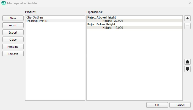
This dialog allows the user to create, import, edit and remove custom filter profiles. Filter profiles are a set of operations which are applied sequentially to a set of soundings. Filter operations can modify soundings in a number of ways, most commonly by rejecting undesirable soundings, but also through modifying flag data or shifting sounding position.
Note that filters run from the Filter Toolbar will set the 'Filter' bit in the QPD when rejecting points. By doing so, we can differentiate these rejected soundings from soundings rejected via manual editing in the Swath, Slice and 3D Editors (these set the 'Manual Edit' flag). This allows you to apply and revert filters using the filter toolbar without being worried about losing any manual editing that may have been done.
The dialog is divided into two main halves: filter profile management happens on the left, while the profiles and their constituent operations are edited on the right. The profile selected on the left dictates which profile is edited on the right.
Profile Management
Profiles List
This list contains all the custom profiles that the user has created or imported.
New
This button creates a new, empty filter profile after asking for a profile name.
Import
This button imports a filter profile from a file. Both Qimera's own .profile format as well as Qloud's .qfd file formats are supported. Please note, however, that not all of Qloud's filter operations have a perfect equivalent in Qimera, so profiles should always be reviewed for subtle discrepancies after import.
Export
This button allows for a profile to be exported into Qimera's .profile format.
Copy
This button duplicates the currently selected profile after asking for a new profile name.
Rename
Renames the currently selected profile after asking for a new name.
Remove
Removes the currently selected profile after asking for confirmation.
Profile Editing
Operations List
This list shows all of the operations making up the current profile along with their editable parameters. Operation names are shown in bold. Operation parameters are shown across two columns with the name on the left and the value on the right. Click on a parameter value to edit it.
Add New Operation
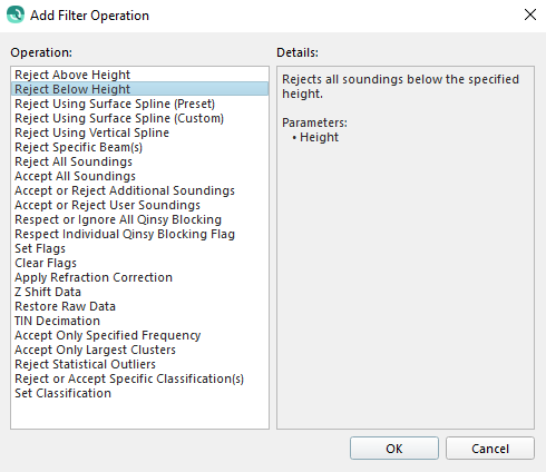
This button shows the Add Filter Operation dialog, allowing you to choose a new operation to be appended to the profile.
This dialog lists the names all of the available operations on the left. Selecting an operation name shows a description of that operation in the Details pane on the right. Click OK to add the selected operation or Cancel to cancel.
This button removes the selected operation from the list.
Move Operation Up
This button moves the selected operation up in the list of operations. Operations higher in the list are executed before the operations that follow them.
Move Operation Down
This button moves the selected operation down in the list of operations. Operations lower in the list are executed before the operations that precede them.
Available Filter Operations
Qimera has several filter operations which can be combined to produce interesting results. See below for a list of all operations and a brief description of what they do.
Reject Above Height
Rejects all soundings above the specified height.
Parameters:
Height
Reject Below Height
Rejects all soundings below the specified height.
Parameters:
Height
Reject Using Preset Surface Spline
Fits a 3D spline surface through noisy point data and rejects all soundings that are too far from the surface. The spline type is chosen from a list of presets.
The 3D spline surface is a representation of the local topography built using approximately 50-100 soundings at a time. The surface is calculated using a weighted least squares method through the available soundings. The surface is area based and takes contributions from many survey lines simultaneously. The criteria for spike detection depends on the expected sounding vertical accuracy, which scales with filter strength. Strong filters filter more data than weak filters.
The ROV Depth is positive downward and is added to the sounding depth (which is most likely negative) to reference the sounding to be relative to the sensor as opposed to the water surface.
The Reference Depth can be used to adjust the reduced soundings to get back to values relative to the water level. This can be used, for example, when working on a lake where the depths can be very large when referenced to mean sea level. The reference depth is subtracted from the reduced soundings.
The Rejection Preference is used to specify which soundings are rejected in relation to the computed spline depth. The options are Reject Above and Below, Reject Above and Reject Below.
Parameters:
Spline Type
ROV Depth
Reference Depth
Rejection Preference
Reject Using Custom Surface Spline
Fits a 3D spline surface through noisy point data and rejects all soundings that are too far from the surface. The spline type is chosen by manually specifying all parameters.
The 3D spline surface is a representation of the local topography built using approximately 50-100 soundings at a time. The surface is calculated using a weighted least squares method through the available soundings. The surface is area based and takes contributions from many survey lines simultaneously. The criteria for spike detection depends on the expected sounding vertical accuracy.
The Surface Spline performs basically the same operation a data processor would do manually: it attempts to determine what the bottom, or a feature on the bottom is, by fitting a surface spline through the noisy footprint data and filtering out any footprints that lie too far away from this surface.This is done in two passes:
The first pass will filter large blunders to create a well-fitting surface spline.
A second pass will filter noise.
The surface spline used in this algorithm is known in literature as a Thin Plate Spline see: (Bookstein, 1989). “The Tin Plate Spline is the two-dimensional analog of the cubic spline in one dimension.” (Belongie)
Parameters:
Minimum Point Count: Increase the minimum point count to allow the filter to better model the seafloor, however this will typically come at the expense of increased processing time.
Expected Sounding Vertical Accuracy: Expected accuracy is expressed in percentage of water depth.
First Pass SD & Second Pass SD: First and second pass SD factor is a scaling factor applied to the standard deviation that controls two consecutive spline fitting passes. Low values filter strongly, high values filter weakly. The first pass SD should not be too high to ensure that blunders are eliminated on the first pass to allow for a better fit on the 2nd pass.
ROV Depth: The ROV Depth is positive downward, and is added to the sounding depth (which is most likely negative) to reference the sounding to be relative to the sensor as opposed to the water surface.
Reference Depth: The Reference Depth can be used to adjust the reduced soundings to return to values relative to the water level. This can be used, for example, when working on a lake where the depths can be very large when referenced to mean sea level. The reference depth is subtracted from the reduced soundings.
Rejection Preference: The Rejection Preference is used to specify which soundings are rejected in relation to the computed spline depth. The options are Reject Above and Below, Reject Above and Reject Below.
The First Pass
A surface spline will be deformed if large spikes are present. In other words, blunders (large spikes in the data) have an effect on the fitted surface. These spikes need to be removed to achieve a surface that fits ‘nicely’.
A surface spline is considered a nice fit, if the RMS of all differences between the surface and the actual points is smaller than the set threshold. This value will be called the deviation in this report and is expressed as Pα.
The threshold is the first filter parameter and is expressed as a percentage (default 0.5%) of the depth.
As the surface is calculated, if the deviation is larger than the threshold, then four points will be removed from the spline dataset:
the footprint with the maximum height,
the footprint with the minimum height,
the footprint with the largest positive difference with the surface
the footprint with the largest negative difference with the surface.
The surface is then recalculated and if the deviation is below the threshold, the surface is determined to be a ‘nice’ fit. However, if the deviation is still above the threshold, the four points listed above are removed again, and a surface will be fitted again. This process iterates until either the deviation target is attained, or more than half of the initial points are discarded.
As soon as a surface with the surface deviation fitting below the threshold is available ('fits nicely'), all points which exceed the threshold are filtered out. The parameter is the first-pass SD factor.
The Second Pass
Once the largest errors are filtered all remaining points are used for new spline surface. This second pass (C2.Pα) is then used to filter out all the soundings with a Standard Deviation difference greater than C2.
Note that points that were filtered in the first pass can be unfiltered in the second pass. This is necessary because the surface that was determined in the first pass was calculated with a reduced dataset.
Filter parameters
To summarize, the Surface Spline filter has four relevant parameters:
The number of points processed at once. If this number is reduced, the filter takes significantly less computation time, but accuracy is affected. Intuitively, one can understand that if not enough points are considered, a local cluster of blunders may be considered as a valid surface. The number of points should be set as high as possible, while a reasonable filter speed is maintained. A higher number of data points will allow the filter to more accurately follow the surveyed terrain.
The first-pass SD factor. Recommended range: [1.0 … 4.0], where 1.0 is a strong filter action and 4.0 a weak one. It is important that this factor is set to such a value that large blunders are eliminated, so it should not be too high. Since the surface spline determined in the first pass is not as accurate as the spline of the second pass, this factor should also not be set too low, to prevent the accidental filtering of valid data points. A good starting point seems to be: 2.0.
The second-pass SD factor. Recommended range: [1.0 … 4.0]. This is the most important parameter in my opinion. Once a surface with a certain difference to the original data points has been determined, this parameter determines if a point is filtered or not.
Approximation factor, expressed in a percentage of the depth. This is similar to the IHO orders that specify a minimal vertical TPU to achieve when surveying. One can say that the expected accuracy of the survey must be used as this parameter.
Reject Using Vertical Spline
Rejects soundings by fitting a vertically-oriented, 3D spline to the soundings and rejecting outliers from that spline.
This filter is only appropriate for filtering vertical surfaces such as quay walls and will work best in combination with an area polygon selection.
The higher the detail of the spline, the fewer soundings will be rejected.
Parameters:
Spline Type
ROV Depth
Reject Specific Beams
Rejects all soundings from the specified beam(s).
In a dual MBES configuration, specified beams are rejected from each system.
If a dynamic surface is created with only one system, the filter will be run only on that system.
The Beams to Disable are specified by a comma-separated list of ranges. For example "1-10, 48, 52, 91-100"
Parameters:
Beams to Disable
Reject All Soundings
Rejects all soundings within the selected area, regardless of their properties.
This is useful primarily for cropping unwanted areas out of a survey.
Parameters: None
Accept All Soundings
"Unrejects" all soundings within the selected area (excluding Additional Soundings).
This clears any filtering, undoes any manual rejection and potentially ignores blocking.
Parameters: None
Accept or Reject Additional Soundings
Accepts or rejects all Additional Soundings within the selected area.
Additional Soundings are soundings that some echosounders report above and beyond the usual number provided by their bottom detection algorithms. For Kongsberg Maritime echosounders, these are call Extra Detections. For Teledyne-Reson echosounders, these are called Multi-Detect.
Parameters:
Action
Accept or Reject User Soundings
Accepts or rejects all User Soundings within the selected area.
User soundings are soundings the user created in the water column view.
Parameters:
Action
Reject All But Specific Frequency
Rejects all soundings that were acquired by a frequency different than the specified frequency. When acquiring bathymetry with multi-frequency sonars such as the R2Sonic multi-spectral sonar, it allows the user to generate a surface using only a specific frequency. The user must use the Revert All Filtering or Clear Flags with Filter option to reset the soundings before performing another use of this filter on a different frequency. This filter is for advanced users and knowledge of the sonar frequencies needs to be known in advance.
Parameters:
Frequency to Accept
Respect or Ignore All Qinsy Blocking
Rejects or accepts soundings by respecting or ignoring the original Qinsy blocking flags.
Any sounding with a blocking flag set will be rejected, unless blocking flags are being ignored (or it has been manually accepted).
Parameters:
Blocking Flags
Respect Individual Qinsy Blocking Flag
Rejects soundings by respecting a particular online Qinsy blocking flag.
Any sounding with the selected blocking flag set will be rejected.
Parameters:
Flag
Set Flags
Sets any of the flags Plotted, Feature, or Suspect for the soundings.
Parameters:
Set Plotted Flag
Set Feature Flag
Set Suspect Flag
Clear Flags
Clears the specified data status flags for all soundings.
Clearing the Manual Edit flag or Filtered flag may cause rejected soundings to become accepted, if no other reason remains for rejecting them.
Parameters:
Clear Manual Edits
Clear Filtered Flag
Clear Feature Flag
Clear Plotted Flag
Clear Suspect Flag
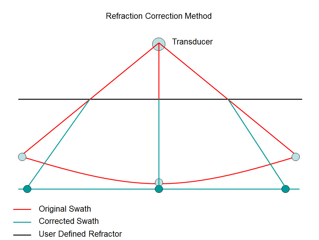
Apply Refraction Correction
Applies an empirical refraction correction based on a simplified refraction model which introduces a sound speed correction at a specified depth level. The idea is to define a 'Refractor' plane below the MBE transducer which delineates the depth at which the refraction correction is applied to the SV profile used during acquisition. When you set a depth of 10 meters, it means that all the depths below 10 meters are affected by the refraction correction. No refraction corrections are applied to depths that are above the specified refractor depth. The following diagram illustrates the basic premise of the filter. The filter can be applied to 'Rejected/Flagged' soundings using the 'Filter Rejected' option. If this option is set to 'No' on 'Accepted' soundings will be filtered.
The refraction correction is stored separately from the corrected sounding and can be reset with the "Restore Raw Data" filter.
Parameters:
Refractor Depth
Sound Velocity Correction
Filter Rejected
Apply Z-Shift Correction
Applies the specified shift to all soundings, moving them in the Z direction.
The shift is stored separately from the corrected sounding and can be reset with the "Restore Raw Data" filter.
Parameters:
Z Shift
Restore Raw Data
Re-enables all soundings disabled by manual editing and filtering and re-disables soundings that were previously blocked but then later re-accepted through manual editing. Can also reset the custom XYZ shift that may have been applied with the Z-Shift filter or the Refraction Correction filter.
Parameters:
Reenable Disabled Soundings
Reset XYZ Shift
Decimate to TIN Vertices
Rejects soundings using a triangulated irregular network (TIN), leaving only those soundings required to capture the shape of the surface.
A coarse TIN is constructed. Triangles are then subdivided by inserting outlier soundings. This process is repeated until no sounding is farther than the tolerances from the mesh. Finally, all soundings which are not part of the TIN are rejected.
Set the Tolerance as % of Depth to zero to disable the relative tolerance.
Reduce the Maximum Link Distance to increase the density of the TIN.
Parameters:
Absolute Tolerance
Tolerance as % of Depth
Maximum Link Distance
Reject Using Clustering
Divides points into clusters and rejects all soundings that do not belong to the largest cluster.
Instead of examining the entire point set at once, it may be divided into smaller subsets. The filter is then applied to each subset independently. The Buffer Size determines the maximum number of points in a subset.
For each subset of points, clusters will be determined. Two points that lie within the Clustering Distance of each other will be grouped into the same cluster. The Clustering Distance must therefore be larger than the 3-D separation between points on the surface and their closest neighbor on the surface. But it should be smaller than the separation between noise points and the surface.
All but the largest cluster for each subset of points will be rejected. Points in clusters with a size smaller than the Minimum Cluster Size will be rejected as well.
This filter works best on a surface with a consistent depth. Steep gradients may lead to a larger than average separation between points on the surface, which may result in erroneous rejection of points on or near the gradient.
Parameters:
Clustering Distance
Minimum Cluster Size
Reject Outliers (True 3D)
Rejects points with large mean distance from its neighbors.
For each point the filter first determines the mean distance between it and its N closest neighbors, where N equals the Number of Neighbors for Mean Distance parameter.
Then it determines the statistical distribution (the mean and standard deviation) of the mean distances calculated in the first step. Finally, the filter rejects all points with a mean distance to its neighbors greater than the overall mean plus a factor times the overall standard deviation. The factor is specified as the parameter Outlier Threshold.
The lower the Outlier Threshold, the more points are rejected by the filter. If the filter rejects valid surface points, increase the threshold.
In order for the filter to work, more points have to be loaded at a time than are actually considered for filtering, because the filter requires neighboring points to be known. How many extra points need to be loaded, depends on the Distance Between Points and the Number of Neighbors. The Distance Between Points is a measure of the distance between a point and its immediate neighbor(s).
This filter works best if the noise in the data is sparsely distributed. If the data contains clusters of high density noise, the filter is less likely to work. For such a data set the filter might be made useful by increasing the Number of Neighbors for Mean Distance.
Parameters:
Number of Neighbors for Mean Distance
Outlier Threshold
Distance Between Points
Reject or Accept Specific Classifications
Rejects or accepts all soundings with the specified classifications. The Classifications to Disable are specified by a comma separate list of ranges. For example "1-10, 48, 52, 91-100". This filter currently only works for LAS/LAZ point file formats.
Parameters:
Action
Classifications
Set Classification
Applies the specified classification value to soundings. Classification values can range from 0 to 255. This filter currently only works for LAS/LAZ point file formats.
Parameters:
Classification
Reject Outside of Intensity Range
Rejects all soundings with an intensity outside the given range. Soundings with an intensity lower than the minimum or higher than the maximum values will be rejected.
Parameters:
Minimum Intensity
Maximum Intensity
Reject Above Uncertainty Threshold
Rejects all soundings above a specified maximum Total Horizontal Uncertainty or maximum Total Vertical Uncertainty.
Note that uncertainties, both horizontal and vertical, are expressed at the 95% confidence level.
Parameters:
Uncertainty Type
Maximum Uncertainty
Reject Specific Quality Values
Rejects all soundings with any of the specified quality values set in the list of ranges.
The quality values to reject are specified by a comma separated list of ranges. For example "1-3, 5, 7-10"
Parameters:
Quality Values to Reject
Reject Outside of Angle Range
Rejects all soundings that lie outside of the set angular range. The beam angle is measured from nadir, positive to starboard. The valid range is -180 to +180 degrees.
This filter is intended for use only with Multibeam or Laser data that has an accompanying raw source file. FAU files are also supported but other processed points files do not have the necessary data fields filled.
Parameters:
Minimum Angle
Maximum Angle
Reject Outliers (1D)
Rejects all soundings greater than the Vertical Threshold distance from a grid mean. The grid is created on-the-fly based on the Grid Resolution parameter.
If the Dynamically Update Grid Cell Depths option is used, as the most extreme soundings are rejected the cell's mean depth will by updated to reflect the remaining soundings.