Local Engineering Coordinate System Setup

On this page:
Local Engineering Coordinate System Setup
This dialog is used to set up a local engineering grid to transform your horizontal coordinates into a local reference frame. This is frequently used in construction operations so that the coordinates are all referenced to a local grid.
Name
The Name field is completely custom and will not have an EPSG code. Enter the desired name for your Engineering Grid.
Datum
The Datum field is also completely custom and will not have an EPSG code. Enter the desired name for your Engineering Grid datum.
Type
Select the type of Engineering Grid that you want to use.
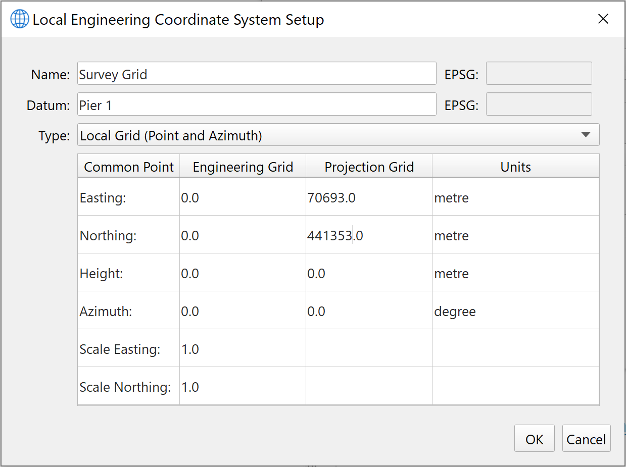
Local Grid (Point and Azimuth)
This is the parameter view for this type. A simple example is that you enter an Easting and Northing coordinate in your survey area such as (4401340.0, 343256.0).
If you leave the Easting/Northing values of the Engineering Grid at 0.0, then the Projection Grid position becomes the (0.0,0.0) location and all other positions are referenced to this point.
It is essentially an Affine transformation to get to the local grid coordinates. You can also add an Azimuth value for both the Engineering Grid and the Projection Grid to get a relative azimuth.
Finally you can use Easting and Northing scaling values.

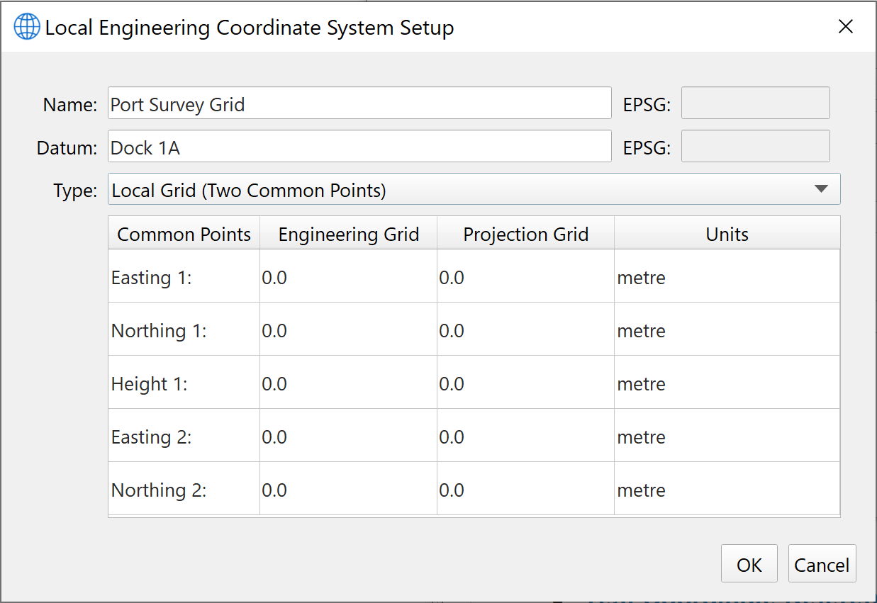
Local Grid (Two Common Points)
This type allows for a 3D reference between the Engineering Grid and the Projection Grid. Simply enter the appropriate values into the table.

