How-to - ARA Beam Pattern Correction
The Beam Pattern Correction menu option opens the dialog shown in the Beam Pattern Correction Dialog figure. It displays the beam pattern of the current virtual "patch" of data, the current theoretical model beam pattern and the beam pattern correction plot which is the difference between the actual and theoretical curves. This how-to page explains what a beam pattern file is, and goes step-by-step through how to first create, and then apply a beam pattern file.
What is a Beam Pattern File?
For FMGT (Geocoder Toolkit), a beam pattern file is an ascii file with 181 rows in it. Each row has three numbers which are:
The beam angle going from port to starboard. 90 (for 90 degrees) is the nadir, and ranges from 0 to 180 degrees.
The amount of energy in dB to add at that angle to correct for the beam pattern
The third argument is currently unused but needs to be there, you can just make it one if you like.
Thus the file will look something like: (Noting that we removed a number of lines, for brevity)
0 -22.54 1
1 -22.54 1
2 -18.30 1
.
.
.
89 10.97 1
90 11.57 1
91 11.41 1
.
.
.
179 -20.71 1
180 -20.71 1
How to Create a Beam Pattern File
Step 1 - Create a Project
Ensure you have the latest version of FMGT installed.
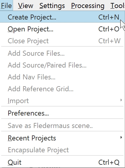
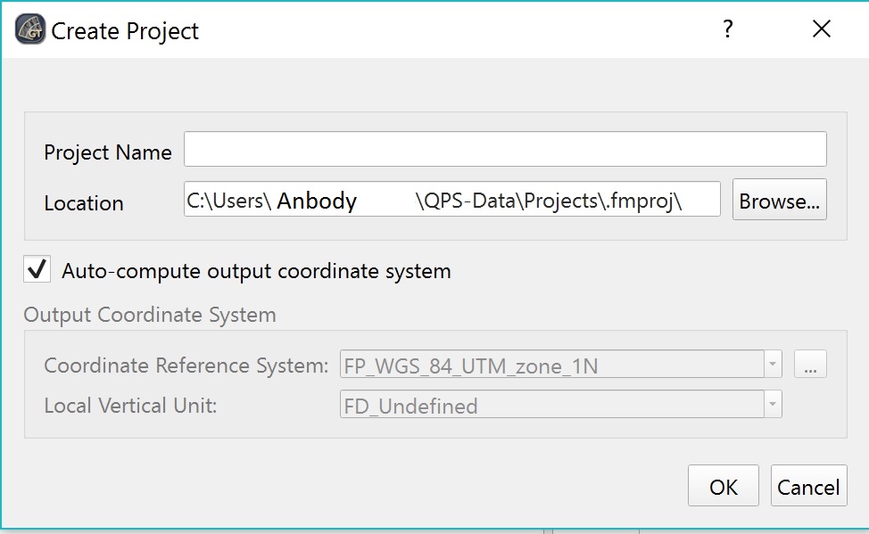
To create a project in FMGT from the File menu click on Create Project. You will then be asked to give the project a name.
Step 2 - Create ARA
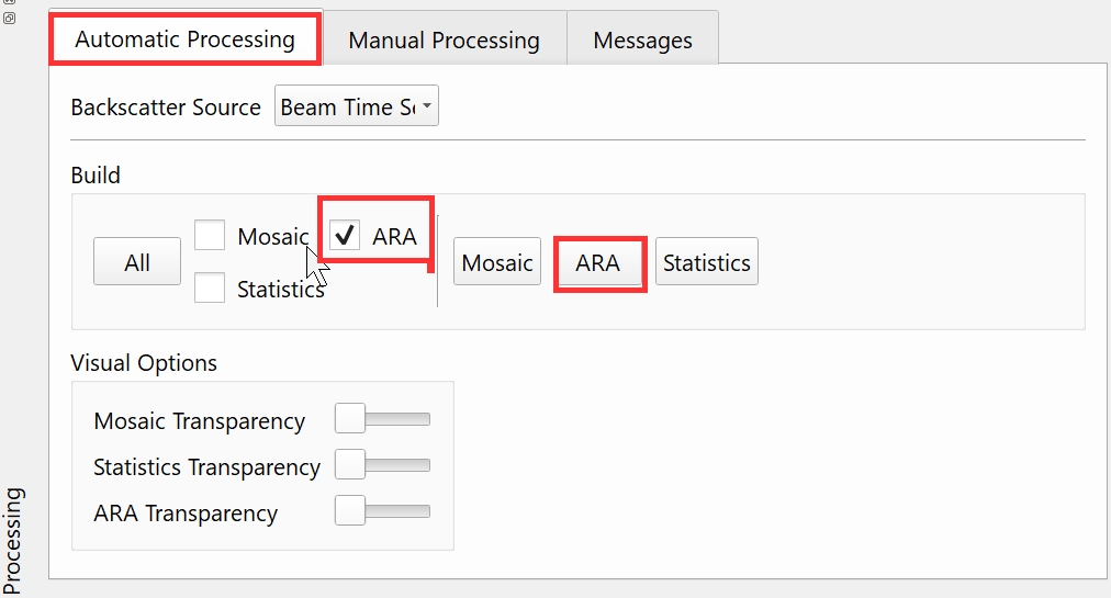
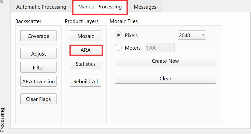
After bringing in your data, create an ARA by either:
Automatic Processing > Build > Check box next to ARA > Click ARA
Manual Processing > Click ARA button
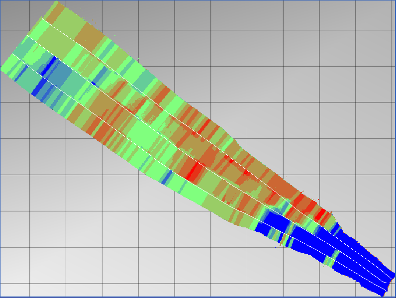
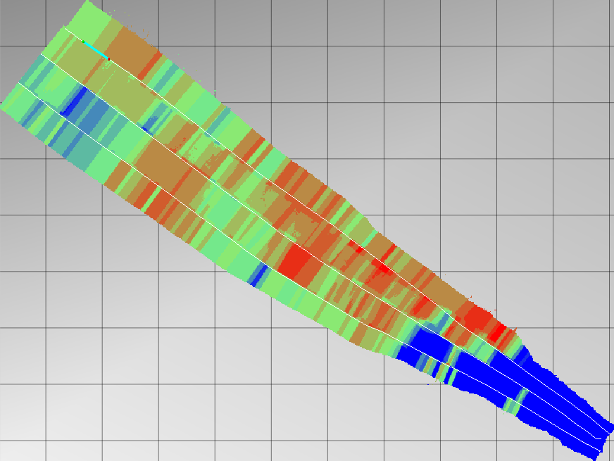
The resulting ARA:
Step 3 - Edit Segment Tool
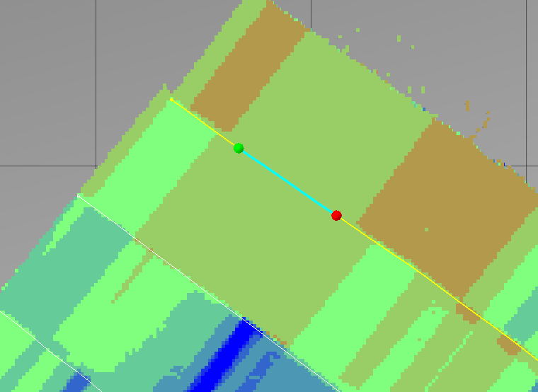
To begin to use the Beam Pattern Correction Tool, use the Edit Segment tool located on the right hand to select Control Panel, a portion of a track line as show in the Edit Selection Tool figure.

Next, you will want to select the line you wish to run the tool on, and choose a short segment to select (ideally a relatively homogeneous area). To do this use the left click to start the line (green dot), and right click to end the line (red dot).
Step 4 - Beam Pattern Correction
Please ensure any core samples you have are properly represented by the end of this step to ensure a more truthful outcome.
There are two different ways to complete this step:
Option 1:
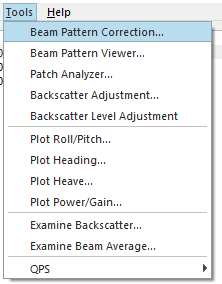
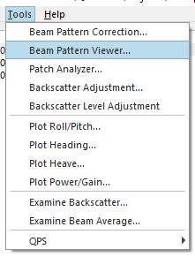
Navigate to the Beam Pattern Correction tool in the Tools dropdown:
When you initially activate the Beam Pattern Correction tool, it will read the selected pings into a virtual patch that can be used by the ARA inversion algorithm.
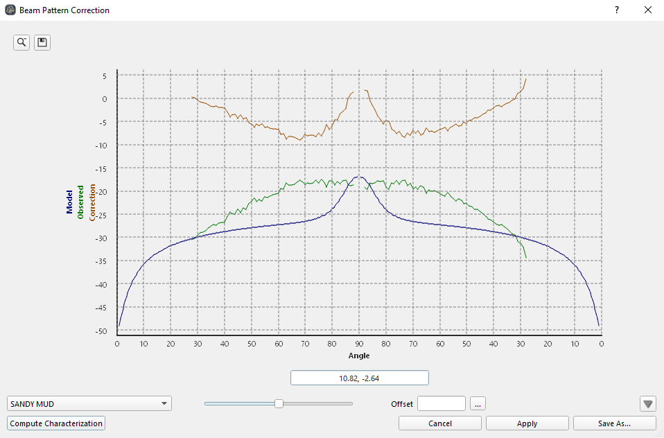
Once the dialog is up, you can either manually select a bottom type (1) or use the FMGT ARA algorithms to compute the proper classification (2). Additional parameters can be manually set by navigating to the down arrow in the bottom right corner (3).
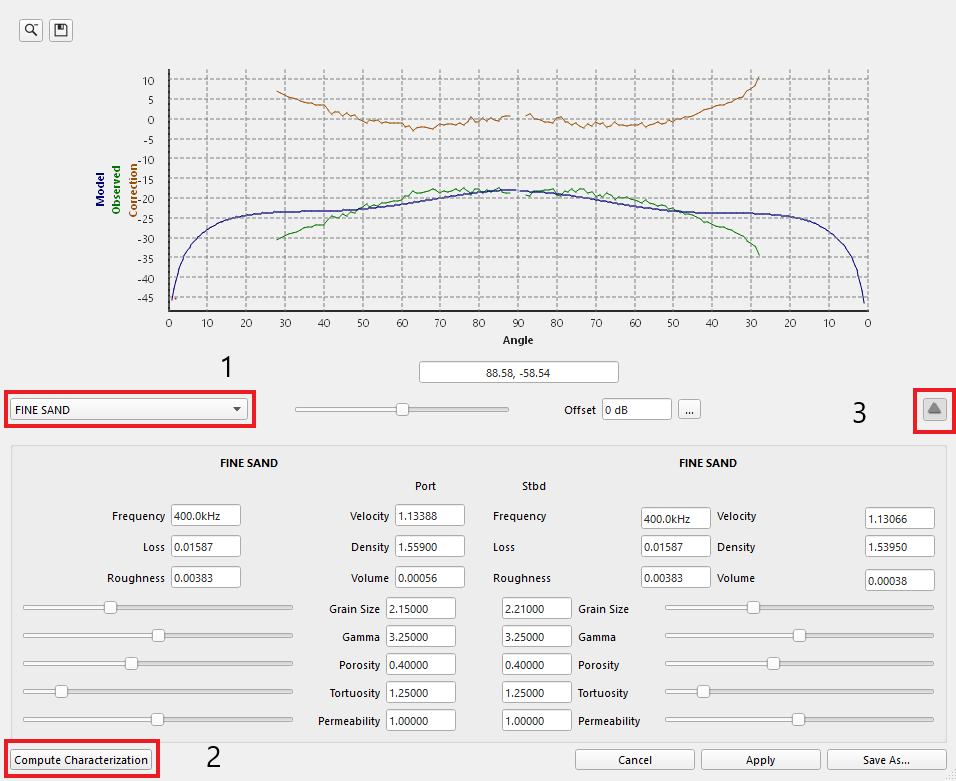
Once you are done, click the save as button in the bottom right. This will allow you to save the beam pattern file.
Option 2:
Use the ARA tab in the bottom right window:
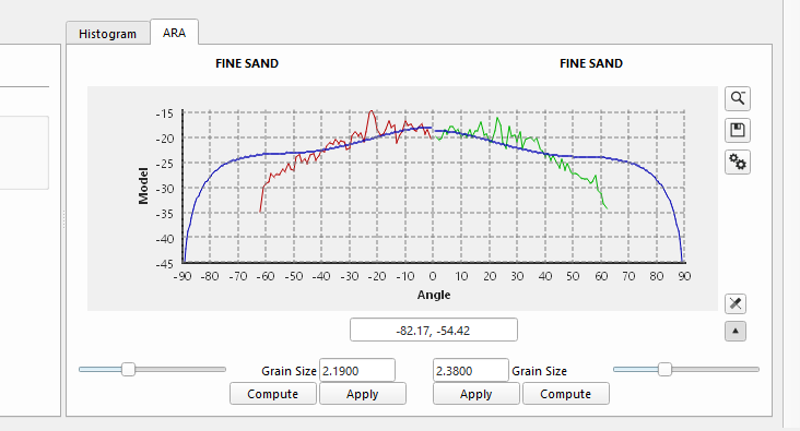
Using the ARA window involves similar steps as the beam pattern correction tool, with options to manually set parameters, as well as automatically compute parameters.
How to Apply a Beam Pattern File
Step 1 - Apply to Data
There are two different ways to complete this step:
Apply button instead of the Save As button in the Beam Pattern Correction window (This option will still save the beam pattern file in the project's ancillary folder).
Load and apply in the Beam Pattern Viewer window:
Open the beam pattern viewer, and click load:
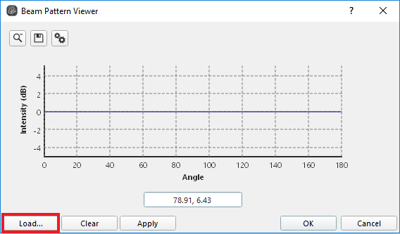
b. Navigate to the saved beam pattern, and once loaded, click apply.
Step 2 - Clear Flags and Recreate Layers
Clear flags (up to adjust) in the manual processing window:

Finally, to see the changes made to the ARA, Statistics, and mosaic, you must recreate them.
For more information on the beam pattern correction tool and the ARA window, visit these pages:
