Vessel Class
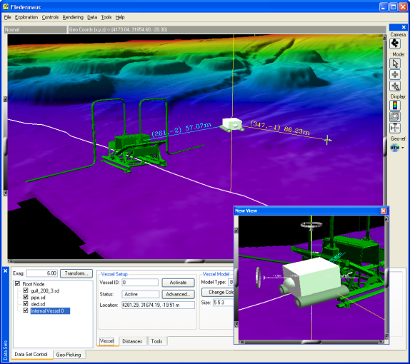
Figure 1 58 - Sample Vessel Screenshot
The Vessel Operations Class allows real-time visualization of a Vessel in a 3D scene. A vessel may be a ship, ROV, AUV, oil platform, or any other vehicle. Vessel data can be read through the serial port, or played back from a pre-recorded file. The VesselManager application, discussed in Chapter 6: Additional Data Tools, must be run at the same time as Fledermaus and is used to process the incoming Vessel information. To add a Vessel to the current scene, select the Data > Add Vessel menu option. In the Data Set Control area, the Vessel interface will appear as shown in Figure 159. Initially, a yellow cross will be drawn in the scene signifying that a Vessel is present, but not activated.
Vessel Tab
To activate the Vessel, enter the id number of the object (found from the VesselManager) in the Vessel ID text field and press the Activate button. The Status text field should change from "Not Initialized" to "Active" if VesselManager is running correctly. To view the VesselManager at any time, click the Show VesselManager button on the right side of the interface. Once activated, the Vessel will appear as a small, white vehicle shown in Figure 158.
As data is read by the VesselManager, the position and orientation of the Vessel will change in real-time. By default, the Fledermaus Main Visualization Window does not continually update so that even though the Vessel is moving, the results will not be shown on the screen. To force the display to continually update, select the Rendering > Interactive menu option. To stop updating the screen, select another option from the Rendering menu. The current geographic location of the Vessel is always displayed in the Location text field.
Each vessel has a single point where the position is recorded, which is called a tracked location (this may be a GPS sensor, or some other device). Usually a Vessel will have a single tracked location; however, if multiple tracked locations exist on the same object, click the Advanced… button to view the Advanced Setup dialog as discussed in section 1.10.4. By default, the tracked location is assumed to be at the center of the object. If this is not the case, use the Advanced Setup dialog to change the tracked location position.

Figure 1 59 - Vessel Controls
A number of options exist for controlling the shape of the Vessel object in the 3D scene. The Model Type drop-down list can be used to select from three different built models: the Basic ROV, a Cube, or a Cylinder. If the Custom type is selected from the list, a custom model can be loaded by clicking on the Load Custom Model button. The custom model being loaded must be a model that was imported using File > Import > Import Model, and then saved as an SD object. Note that when saving a model as an SD object, the model should be facing the positive x-axis (this can be changed using the Transform Vertices button in the Solid Model interface).
The width, height, and depth of the Vessel can be specified in the Size text field. All measurements are given in the units of the scene. Click the Scale button, enter a value in the resulting dialog, and press Enter to uniformly scale the Vessel by that value. For example, if the size was '10.00 10.00 6.00', clicking the Scale button and entering '2.0' into the textfield and pressing Enter would cause the size to become '20.00 20.00 12.00'. To change the color of the Vessel, press the Change Color button and select a color using the standard color selection dialog. Note that the vertical exaggeration of the scene should be set to 1 when comparing distances between the model and the scene.
In the display group, click the Show VesselManager to display the VesselManager application which is used to configure the incoming vessel information. While visualizing the scene, having multiple views of the Vessel can be quite useful. To display an additional view, click the Show View button. This button opens another window that is, by default, constantly focused on the Vessel. To change the how the view is displayed, click the Options… button (see Section 1.10.6 for more information). Again, the display will not continually update unless in Interactive Rendering mode. A monitoring dialog can be displayed by clicking the Show Monitor dialog. This dialog displays important information about the Vessel and is discussed in Section 1.10.5.
Vessel Distances Tab

Figure 1 60 – Vessel Distances Tab
The Vessel Operations Class allows monitoring the distance between a point on the Vessel and any point in the scene. Each distance monitor is displayed as a row in a table on the Distances tab. Click the Add Distance Monitor to add a new distance monitor to the bottom of the list, or select a row and click the Remove Distance Monitor button to delete a monitor.
Each distance monitor by default measures from the center of the Vessel to another point in the scene. To measure from another point on the Vessel instead of the center, enter an offset in the Local Offset column in the units of the data. For example, if an arm of an ROV is located 3 meters to the right, 2 meters forward, and 1 meter up from the center of the vessel, enter a Local Offset of "3 2 1" to measure from that point.
The point in the scene that the distance monitor measures to changes depending upon the value of the Distance Type column:
Pick Point – Measures to the current pick point in the 3D scene. Select a new pick point by entering Select mode in the main display and then clicking a point in the scene. The current pick point location will be displayed in the Target Location column.
Object – Measures to the center of another object in the scene. Choose the other object using the Target Object drop-down list. To measure to another point on the target object instead of the center, enter an offset in the Target Offset column (as you would in the Local Offset column).
Line Object – Measures the minimum distance from a point to a 3D lines object. Select a lines object in the Target Object drop-down list to measure to that object. This option is useful if a 3D lines object exists that indicates the shoreline of a river or ocean, then a distance monitor of this type can indicate how close the vehicle is to the shore.
Fixed Point – Measures to a fixed point in the scene. Enter the coordinates of the target point in the Target Location column.
Vertical – Measures the distance vertically from the Vessel to the sea floor.
Line Object (+/-) – Similar to the Line Object distance monitor, except displays a positive distance if the vessel is to the right of the line or a negative distance if the vessel is to the left of the line. This monitor is useful to measure the deviation of a vessel from a planned path.
If the Visible toggle is turned on for a distance monitor, a line will be drawn in the scene from the point on the Vessel to the target point. The color of this line can be changed by clicking the rectangle in the Color column and selecting a new color. The line width can be changed by entering a new value in the Line Width column. On most of the distance monitor lines in the 3D scene, three numbers will be displayed: the compass bearing in degrees from the Vessel to the point, the elevation angle to the point, and the distance in meters to the point. Some distance monitor types only display the distance in meters. The distance for each distance monitor is also displayed in the Distance column, as well as in the Monitor dialog (see Section 1.10.5).
If a non-zero value is entered in the Warning Distance column, then the distance line in the 3D scene will be displayed as a bold red line if the measured distance falls below the warning distance. The distance will also be displayed in a red font in the Monitor dialog. Use this option to warn if a vessel gets too close to another object in the scene.
Clicking the Load Points of Interest button allows easily setting up a number of Fixed Point distance monitors to points in the 3D scene. Click the button and select an XYZ file containing the list of points to measure to, and the distance monitors will be automatically created.
Vessel Tools Tab

Figure 1 61 – Vessel Tools Tab
A number of additional tools for the Vessel Operations Class are located on the Tools tab at the bottom of the interface. The History section allows displaying a line indicating the path the Vessel has taken in the 3D scene. Display the history line by enabling the Visible toggle. The amount of time the history line indicates can be controlled by entering a value in the Max. Length field in seconds and pressing Enter. Clicking the Create Line Object button converts the current history line in a new SD lines 3D object that will appear in the object list.
A profile can be displayed that tracks the Vessel by using the Profile group. If the Visible toggle is enabled, the profile will constantly update and the profile window will constantly be shown (note the Visible toggle must be disabled before the profile window can be hidden). By default, the profile is locked to the center of the Vessel. To lock the profile to another point, enter an offset in the Offset field. The offset is in units of the scene and indicates the offset right, forward, and up from the center. The Length field indicates the length of the profile, and the Rotate field can be used to rotate the profile to different angles. For example, an angle of 0 means cross-track and an angle of 90 means along-track. More options for the profile can be controlled by clicking the Advanced button, as discussed in Section 1.10.7.
The Prediction group allows displaying a line in the 3D scene indicating where the Vessel will be in the future. Enable the Visible toggle to display the prediction, which appears as a straight dotted white line in the scene. The length of the line can be controlled using the Length text field. The prediction line will not be displayed properly unless your input format contains the 'course made good' field.
Vessel Advanced Setup Dialog
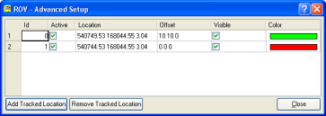
Figure 1 62 – Vessel Advanced Setup Dialog
The Advanced Setup dialog is used to configure options for the tracked locations (or sensors) on a Vessel, and is show in Figure 162. Display this dialog by clicking the Advanced button in the Vessel Setup group.
Each tracked location is displayed as a row in the main table of the dialog. Enter an Id number for the tracked location that corresponds to the number setup in VesselManager. Clicking the Active toggle will activate or deactivate that sensor. The current position of the tracked location will be displayed in the Location column when in Interactive rendering mode.
By default, the tracked location is assumed to be at the center of the object. If the tracked location is not at the center, enter an offset in the Offset column. The units for the offset are in the units of the scene and indicate the amount right, forward, and up from the center of the object.
To display the tracked location in the 3D scene, enable the Visible toggle. The location will be drawn as a diamond and the color can be changed by clicking on the Color column and selecting a new color.
Usually, a Vessel will only have one tracked location; however, some Vessels may have multiple tracked locations (for example, an oil rig might have a tracked location on each of its pylons). Add a tracked location to the bottom of the list by clicking on the Add Tracked Location button, or remove a tracked location by clicking on a row in the table and clicking the Remove Tracked Location button. Note that each tracked location should have a separate Id number and a separate Offset. The first tracked location is used for the position of the vessel, but the other tracked locations are useful for showing the Vessel prediction.
Vessel Monitor Dialog
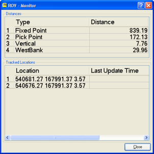
Figure 1 63 – Vessel Monitor Dialog
The Monitor dialog, as shown in Figure 163, is displayed by clicking the Show Monitor button. This monitor displays important information about the Vessel in a large font. The top part of the dialog displays each distance monitor as set up with the Distances tab. The Type and Distance for each monitor is displayed and will update continuously when the scene is in Interactive Rendering mode.
The bottom half of the dialog displays the list of tracked locations for the object. Additional tracked locations can be added to the object by clicking the Advanced button (see Section 1.10.4). For each tracked location, the current Location is displayed, as well as the last time the position was updated in the Last Update Time column (note that the Last Update Time is valid only if proper time information is contained in your input format).
Click the Close button to hide the monitor.
Vessel Display Options Dialog
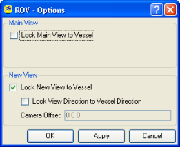
Figure 1 64 – Vessel Display Options Dialog
Figure 164 shows the Display Options dialog that is used to configure how the camera in the main display and extra view will work. This dialog can be accessed by clicking the Options button in the Display group on the main Vessel interface.
If the Lock Main View to Vessel toggle is enabled, the main Fledermaus window will always be centered on the Vessel. The options in the New View group apply to the extra view of the scene that is displayed when the Show View button is clicked in the main Vessel interface. When the Lock New View to Vessel toggle is checked, the view is always centered on the Vessel (this is on by default when the Show View button is clicked). When the view is centered on the Vessel, the view direction can also be locked to the Vessel by enabling the Lock View Direction to Vessel Direction toggle. When this toggle is enabled, the extra view shows an image as if a camera is positioned on the Vessel. The position of the camera can be controlled by entering an offset in the Camera Offset field. This offset indicates the number of units right, forward, and up from the center of the Vessel where the camera is located.
Note that when an option is changed in this dialog, the change will not take effect until either the OK or Apply buttons are clicked. The OK button applies the changes and closes the dialog, the Apply applies the changes without closing the dialog, and the Cancel button closes the dialog without making any changes.
Vessel Advanced Profile Dialog
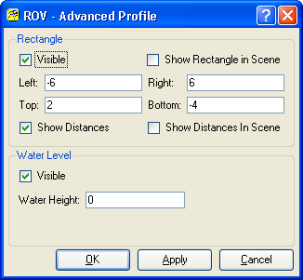
Figure 1 65 – Vessel Advanced Profile Dialog
A profile can be set up which follows the Vessel as it moves (see Section 1.10.3). Clicking the Advanced button in the Profile section of the Tools tab displays the Advanced Profile dialog, shown in Figure 1 65.
This dialog allows some extra information to be added to the Profile Window. Enable the Visible toggle in the Rectangle group to display a rectangle indicating the bounds of the Vessel. Input the horizontal bounds by entering the distance from the center of the object in the Left and Right text fields. Enter the height above water level for the top and bottom of the vessel in the Top and Bottom text fields. For example, if the Vessel ranged from 2 meters above the water to 4 meters below the water, enter 2 and --4 in the Top and Bottom text fields respectively. If the Show Distances toggle is checked a yellow line is drawn from the bottom corners of the rectangle to the profile. This option could be used to tell how much a ship could move left or right before hitting the banks of a river. If the Show Rectangle in Scene or Show Distances in Scene toggles are enabled, the rectangle or yellow distance lines are drawn in the actual 3D scene.
A line indicating the water height can be displayed by clicking the Visible toggle in the Water Level group. The water level will appear as a light blue horizontal line in the profile. Enter a new water height in the Water Height text field.
Note that before any changes are applied to the profile, the OK or Apply button must be pressed. The OK button applies changes and hides the dialog, the Apply button applies changes without hiding the dialog, and the Cancel button hides the dialog without making changes.
Return to: Reference Manual
