
DMagic Tools Menu
DMagic Tools Menu
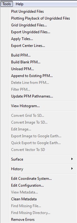
DMagic Tools Menu
All tools apply to the currently selected files and are also available from right clicking on the data object, or from right clicking in the graphical area.
Plot Ungridded Files
This command will plot the points of the currently selected ungridded files in the current view. If there is an active selection box, then only points within those bounds will be plotted. Plotting points will activate the plotting toolbar as shown in the figure below.
DMagic Plotting Toolbar
The toolbar has the following commands:
Cell Size: This value is used to set the size of the 2D grid. This value will also be used as the default cell size if the gridding wizard is launched.
Update Cell Size: This button will replace the current grid with a new grid set to current cell size.
Value to Plot: By default the depth value will be plotted, however any additional value available in the source files can also be used.
Toggle Grid: This will toggle on or off a 2D grid set to the size of the current cell size.
Point Size: This slider will adjust the size of each individual plot point.
Re-plot: This button is used to re-plot the points after the user has either moved the camera position, or has adjusted the value to plot.
Close: This will close the plotting toolbar and clear any currently plotted points.
Plotting Playback of Ungridded Files
This tool will use the selected ungridded files and open a new dialog to show a playback of plotting the soundings as they are read from the selected files.
Replot: Will clear the plotted points and show the playback of plotted soundings again.
Zoom In: If an area is selected the view will change to only encompass the selected area.
Reset View: Resets the view to encompass all plotted soundings.
Close: Close the dialog.
Grid Ungridded Files
DMagic Gridding Wizard (Stage 1)
The grid ungridded files command is used to create a new gridded SD file from one or more un-gridded files. If there is an active selection box, those bounds will be used as the default bounds. The DMagic Gridding Wizard (Stage 1) figure above shows the first stage of the gridding wizard.
DMagic Gridding Wizard (Stage 2)
Below the file type display is a table displaying all the input fields for the current input files. The Mapping column indicates how a given field is used during the gridding process. By changing the Mapping values, different fields can be used for both the value to grid as well as the X and Y value. In addition to changing what fields are used, any field can also be inverted by setting the Modifier column to Invert.
The second tab in the configuration dialog is the Flags control that is used to specify which input flags are used to reject data during the gridding process. This table contains two columns. One to display the flag name, and another to specify whether to accept or reject data that has the given flag set to true.
The second stage of the wizard is displayed in the DMagic Gridding Wizard (Stage 2) figure, and has a number of different options for controlling the gridding algorithm. The Gridding Parameters section controls how a set of points are gridded. The most important parameter when gridding data is the Cell Size, which determines the dimensions of the surface to be created. These dimensions are determined by taking the range of the input data in the X and Y dimensions, dividing it by the cell size, and rounding up.
The Gridding Type pop-up menu specifies which algorithm to use when gridding. There are three types of surfaces that can be used from irregularly spaced XYZ data:
- Weighted Moving Average – the default weighted average algorithm
- Shallow Biased – minimum value in the cell
- Median Filtered – median value in the cell
- Deep - the deepest value in the cell
- Root Mean Square - uses a RMS algorithm
DMagic Gridding Wizard (Stage 3)
The next stage of the gridding wizard is used to specify the color map and shade parameters used to build the SD file. This stage of the wizard is displayed in the DMagic Gridding Wizard (Stage 3) figure above.
DMagic Gridding Wizard (Stage 4)
The last stage of the gridding wizard is used to specify the output filename and if the output should be a surface SD file (SonarDTM) or a scalar SD file. This stage of the wizard is displayed in the DMagic Gridding Wizard (Stage 4) figure above.
Export Ungridded Files
This command is used to export ungridded files to another format. It will launch the export wizard as displayed below.
DMagic Export Ungridded Data Wizard (Stage 1)
The first stage of the wizard is used to confirm which files will be used during the output process. Any file that you do not want to be exported can be disabled using the checkbox located to the left of the file name.

DMagic Export Ungridded Data Wizard (Stage 2)
The second stage displays the current coordinate system of the files being exported and the coordinate system that the exported files will be written to. If the output coordinate system is different than the input coordinate system, each point will be projected during the creation of the output file.

DMagic Export Ungridded Data Wizard (Stage 3)
The third stage gives the option of which output format to write to. If Generic ASCII is chosen then all supported fields read from the input file will be written to the output ASCII file. If any other format is chosen an option is given to specify which field value from the input file will be written as the 'Z Value' to the output file.
All input files can be merged into a single output file.
Each input file can be converted into a matching output file. In this case the use specifies an output directory, and the output files will be created using the same base name as the input files, except with "_out" added to the filename and the extension changed to match the selected output format.
Apply Tides
The Apply tides operation allows offsetting the height of all soundings in an input file according to a tide information file. The tides can only be applied to a set of FAU or FU2 input files using a tide file in Nivel format. The Apply Tides dialog as shown in the figure below will be displayed.
To add a tide file to the list, click the Add Station and button and select a file or files using the standard file select dialog box. The tide files must currently be in Nivel format. A tide file may contain a number of Stations, which are positions where the tide is recorded. To remove a tide file from the file, select the file and then click the Remove Station button. Note that position information is not currently supported in the Nivel format. Click the OK button to begin the tiding procedure, or click the Cancel button to close the dialog without applying and tides.
When the tides are applied, each of the soundings in the input files are read. If a timestamp for the sounding can be found in the tide file, the sounding height is offset by the tide value. The input files are written to new files with '-tided' appended to the file name. For example, tiding the file 'file001.fau' would generate the file 'file001-tided.fau'. If the timestamp for any of the soundings cannot be found in the tide files, an error is generated and the tiding operation is halted.
Export Center Lines
Exports all the Center Lines from the selected Ungridded files to one SD 3DLines file.
Build PFM
The PFM Wizard provides a user friendly and efficient interface for the creation of PFM data sets. The following sections will outline the steps required for building a new PFM with the wizard, appending new data, and unloading an edited PFM.
Input Files and CUBE
The first stage of the wizard is used to confirm which files will be used during the output process. Any file that you do not want to be exported can be disabled using the checkbox located to the left of the file name.
Note that from version 7.4.5 the check box 'Use Auto-Processing (CUBE)' has been moved to the CUBE stage of the wizard.
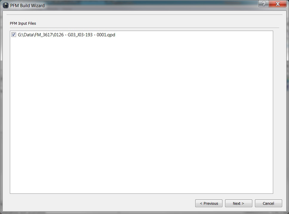
PFM Build Wizard (Stage 1)
Coordinate System
The second stage of the wizard is used to setup the coordinate system for the PFM by displaying the coordinate system for both the ungridded input files and the output PFM. If the PFM is set to a different coordinate system than the input files, DMagic will project each data point into the PFM coordinate system.
Bounds
Once the coordinate system has been configured, the next stage is used to specify the overall bounds for the PFM data set as shown in the PFM Build Wizard (Stage 2) figure below. By default the toggle Auto-Scan on Load is set to true, which means that no other set up is required for this stage - before the actual loading is started, the Wizard will scan all the input files in order to determine what bounds to be used. Alternatively, if the Auto-Scan on Load toggle is turned off, the bounds need to be specified at this stage. The bounds can be obtained by either loading an ISS-60 formatted area file (usually with extension ".are") using the Load From File button or the Scan Now button can be used to perform a full scan of all the input files. An ".are" file is a simple ASCII file consisting of four lines similar to that shown below.
N 30.26428, W 90.46645
N 30.26428, W 89.60689
N 29.95703, W 89.60689
N 29.95703, W 90.46645
The system will actually use the minimum bounding box that encloses all four corners for the PFM area. Once either option has completed and the bounds displayed, they can be manually adjusted by replacing any value in the bounds fields.
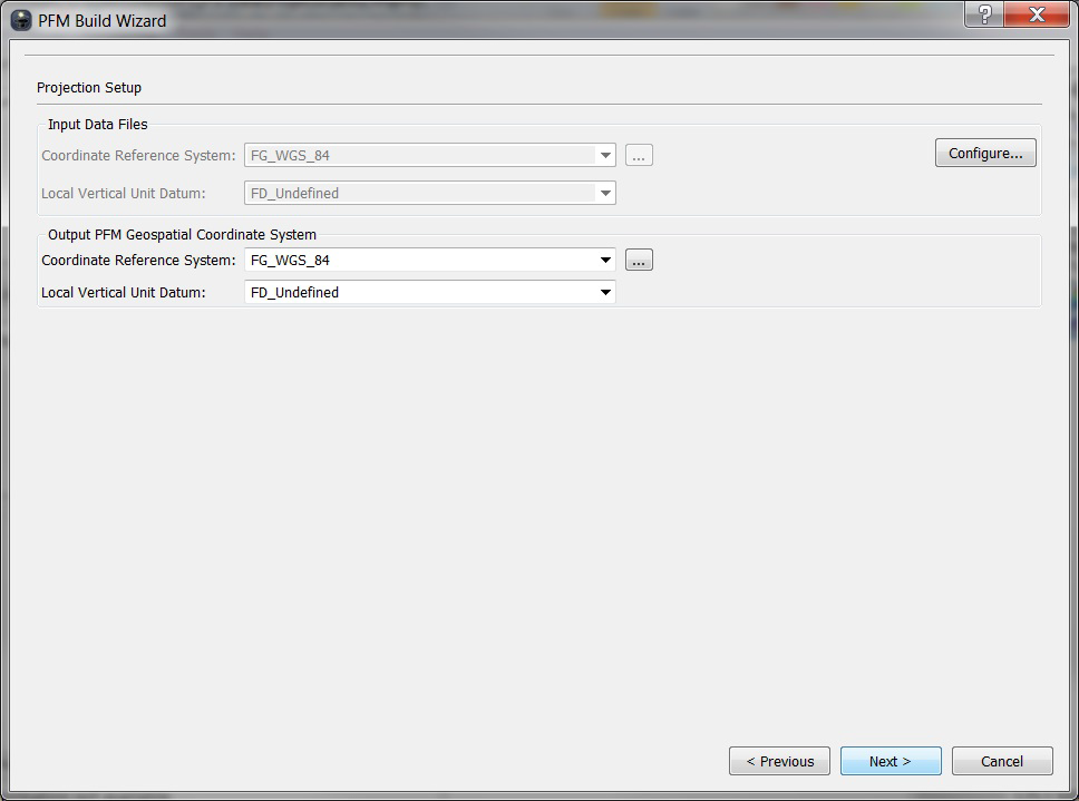
PFM Build Wizard (Stage 2)
PFM Configuration
The PFM configuration stage of the wizard is used to specify some of the build parameters for the new data set. At the top left of the wizard is the XY Bounds selection box which is used to specify the approximate XY range of the PFM. This can be automatically set by the bounds of a selected area from within the Display Area. If no selection is made then the bounds are filled based on the XY range gathered from the metadata of the selected files. If no selection is made, and metadata has not been generated for all selected files, then the XY bounds are left blank. There is the option to always scan for XY bounds during the build process of a PFM if 'Auto Scan on Load' is checked.
Z-Range selection box, which is used to specify the approximate depth range for the PFM. In addition to the four preset ranges, there are two other options – Custom and Auto. When set to Auto, the application will scan the data during the build operation in order to determine what is the exact depth range of the input data. The last option, Custom, can be used to set a user defined depth range for the PFM.
The Bin Size field is used to specify the size of each cell used in the PFM binned data structure. Note that the binning has no affect on the underlying sounding data, which is always stored at full resolution.
The Vertical Resolution field is used to select a resolution close to the expected vertical resolution of your data. The less resolution used, the less space the PFM will require.
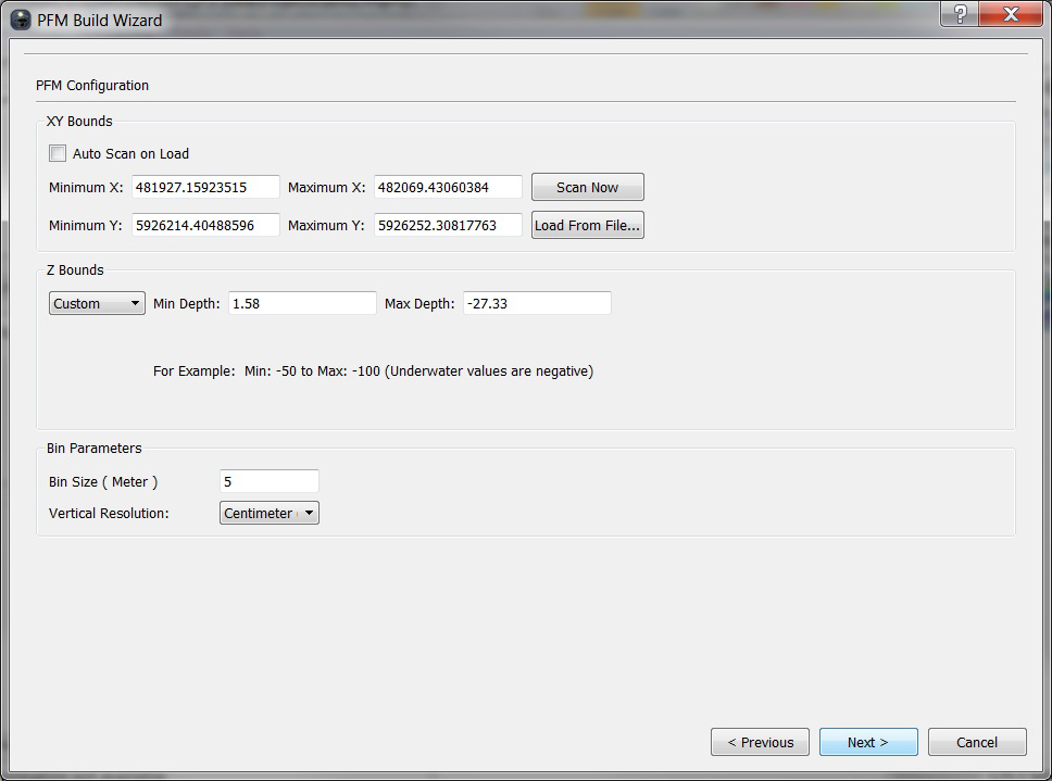
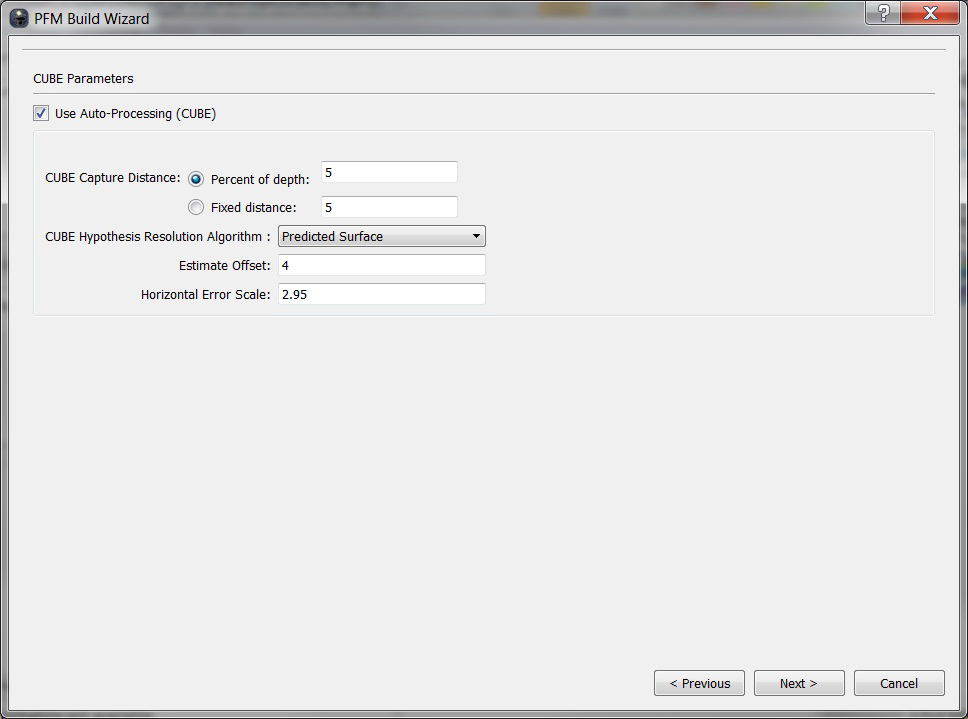
PFM Build Wizard (Stage 3)
CUBE Parameters Setup
The CUBE processing option has been moved to this stage. Check the `Use Auto-Processing (CUBE)' checkbox to enable CUBE and allow editing of the CUBE parameters.
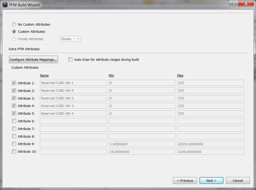
PFM Build Wizard (Stage 4)
Extra Attributes
In addition to the standard PFM data, ten additional attributes can be selected and included with the data set using the Wizard stage displayed in the PFM Build Wizard (Stage 4) figure below. This stage is optional and by default will not be displayed.
To include an extra attribute, the toggles on the left side of the Wizard can be turned on. When creating a PFM with input files from two or more different file types, only the format of the first input file added will be used. The next step is to select the attribute from the source format that will be included in the PFM using the "Configure Attribute Mappings…" button. It is important to note that although a particular attribute may be included in a format, there is no guarantee that the source files actually have that field populated with real data. If the PFM is build with CUBE, the first five attributes are reserved for CUBE attributes.
Preset attributes can also be selected which will automatically use the appropriate attributes and ranges for a selected configuration. Once this option is toggled, just select which configuration you want to use from the drop down menu, and hit the "next" button.
Currently there are 3 preset configurations to choose from:
SHOALS
Attribute | Min Range | Max Range |
|---|---|---|
AB Depth Conf. | -100 | 100 |
Sec. Depth | -1000 | 400 |
Intensity | 0 | 255 |
LADS
Attribute | Min Range | Max Range |
|---|---|---|
Row | 1 | 18 |
Column | 1 | 48 |
Contender Depth | -99 | 99 |
LADS DB
Attribute | Min Range | Max Range |
|---|---|---|
Row | 1 | 25 |
Column | 1 | 98 |
Run | 0 | 100000 |
Section | 0 | 99 |
Sequence | 0 | 99 |
Segment | 0 | 99 |
Segment Status | 0 | 20 |
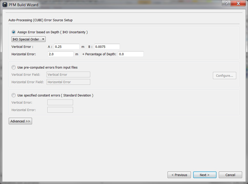
PFM Build Wizard (Stage 5)
CUBE Error Parameters Setup
This stage allows you configure the CUBE error parameters.
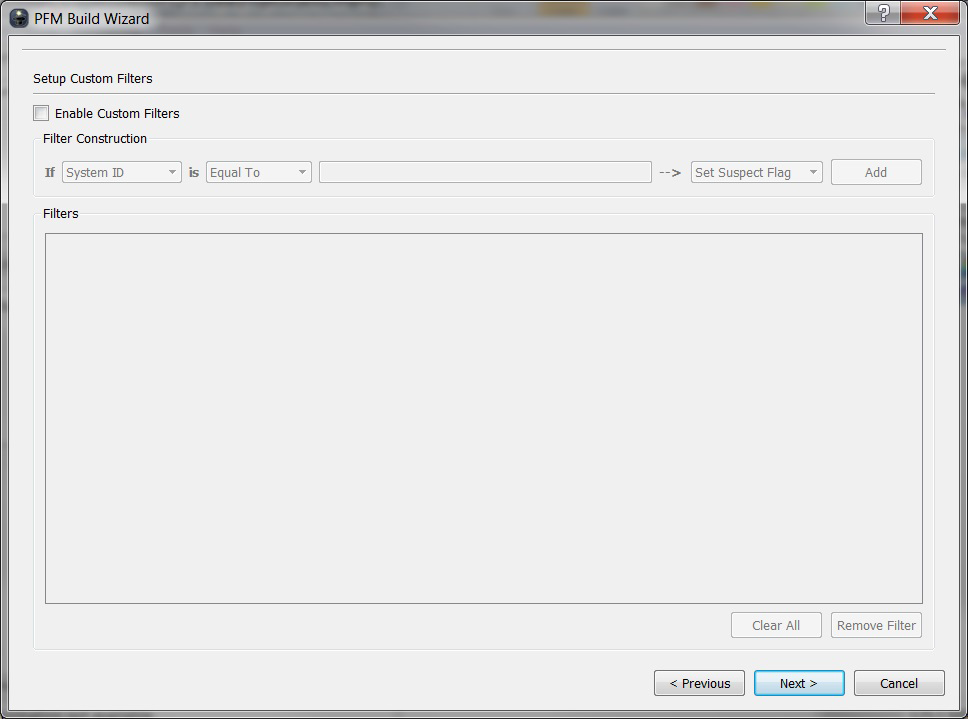
PFM Build Wizard (Stage 6)
Custom Filters (optional)
The Custom Filters stage allows running filters on the individual soundings when the PFM file is built. By default, no filters are used when building the file. To enable the use of filters, click the Enable Custom Filters toggle.
Each filter has a Condition and an Action. If a sounding matches the condition, then the action is applied to the sounding. Conditions are constructed by comparing the value of one of the attributes of the file with a given value. Select the attribute to compare in the drop-down list to the right of the If label. Select the comparison method with the drop-down list to the right of the is label (options include Equal To, Greater Than, Less Than, Not Equal To). Enter the value to compare in the field to the right of this drop-down list. If the condition is met for a sounding, then an action is applied to the sounding according to the drop-down list to the right of the '-->' symbol. The action can either set one of the flags in the PFM file, or can exclude the sounding from the PFM file.
Once a condition and action has been chosen, click the Add button and the filter will be listed in the Filters list box. Only those filters listed in the Filters list box will be applied to the data when the PFM file is built. Select a filter from the list and click the Remove Filter button to delete the filter from the list. Click the Clear All button to delete all filters from the list.
PFM Build Wizard (Stage 7)
Final Stage and Area Based Filter
Before starting the build process, the location for the PFM data set needs to be specified. The only required input at this stage is the file name and location for the PFM list file – both the Bin and Index file names will be automatically created based on the list file. If desired, the path can be customized to accommodate a custom configuration. This stage of the wizard can also be used to select both an optional target file and an optional image file.
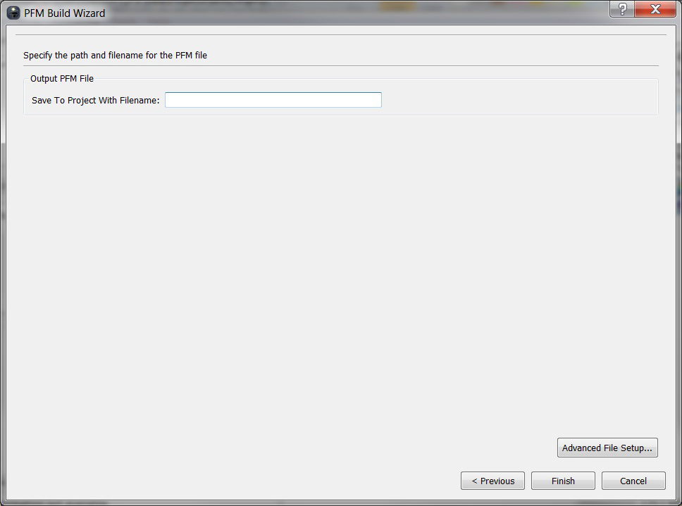
PFM Build Wizard (Stage 8)
The last stage of the wizard provides a confirmation of the PFM list filename and path. The Finish button in the lower right of the wizard can then be used to start the build process, during which a progress window will provide updates on the progress of the build.
The last stage of the wizard provides the option to activate and configure the area-based filter. If enabled, the filter will automatically begin once the PFM data set has finished building. Specify the standard deviation threshold for each cell in the Cell Std. Deviation field.
Build Blank PFM
The Build Blank PFM is used to build a PFM data set without adding any initial data files. This allows a blank PFM to be set up as the first step before adding data using one or more Append operations. Please refer to the previous section on the PFM Build Wizard for a description of the options used when building a blank PFM.
Unload PFM
Once you have edited a PFM data set in Fledermaus, the edits that have been temporarily stored in the PFM can be applied back to the original source files using the Unload PFM option. In order to support unloading the original format must have validity flags that can be updated.
Append PFM
Additional source data can be added to an existing PFM by using the append operation. The primary requirement for this operation is that the new data must be within the bounds of the PFM, otherwise any data that is outside those bounds will not be included.
Delete Line from PFM
PFM Delete Line Dialog
There is often the case when you need to delete one or more lines from a PFM but do not want to rebuild the entire data set. The Delete Line utility allows you to select one or more lines from a PFM and have the data records from those files removed from the data set. Once the data is removed, the bin values are recalculated to include only the remaining data.
Filter PFM
If you have an existing PFM that you would like to clean using the Area Based Filter (as described in section 5.5.5) the Filter PFM menu option can be used. Once selected, a wizard will launch in order to guide you through the steps of using the area based filter.
Update PFM Pathnames
Update/Verify PFM command launches a dialog to edit the internal hardcoded pathnames within a PFM file. This is needed when a PFM has been moved from it's original location, or it's source files have been moved.
View Histogram
This command will display a histogram for the currently selected un-gridded data file, or the current active group of files. The currently active attribute that is displayed can be adjusted using the Variable combo-box located at the bottom of the dialog, as shown in the figure below.
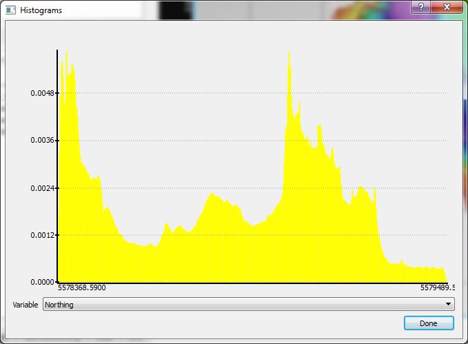
View Histograms Dialog
Convert Grid to SD
Convert Grid to SD Wizard (Stage 1)
The Convert Grid to SD command is used to convert any supported source grid file into either a surface (SonarDTM) surface SD file, or a Scalar SD file. The first stage of the wizard displays the following options:
- Invert Z Range: This toggle will invert the z value of the incoming grid.
- Use User Defined Z-Range: By default the grid will be imported using the full z range of the file, however a custom z-range can be provided to restrict the values.
Output Coordinate System:Specifies the coordinate system for the resulting SD file.
Convert Grid to SD Wizard (Stage 2)
The second stage of the wizard is used to specify the colormap and the shade parameters that will be used when shading the imported grid. Default shade parameters are what's specified in the DMagic preference or the parameters can be loaded from a Shade Parameters file.
Convert Grid to SD Wizard (Stage 3)
The last stage of the wizard is used to specify the SD type (Surface DTM or Scalar) and the file name for the SD file.
Convert Image to SD
This menu option will open a Save File Dialog to specify the name of the SD file that the selected image will be saved to.
Edit Image
The Edit Image command is used to perform a wide array of operations directly on raw image data. When this command is activated, the overall DMagic interface is modified and the Edit Image Toolbaris displayed. While in the image editing mode, all non image operations are disabled and only the currently active image is displayed in the display area.
DMagic Edit Image Toolbar
Save
The Save command will update the currently active image file with any changes that have been made since the file was opened in the image editor.
Save As
If you want to save the current image to a new file, the Save As command can be used. Any editing operations done after using this command will be applied to the new image file.
Write TFW
The Write TFW option allows you to write the current geo-referencing data to a tiff world file.
Undo / Redo
The Undo and Redo items which become active only when it is possible to undo the last action or redo the last action (that is, undo the last undo).
Mode
The Mode options changes the image representation between RGB, that is 3 channels: red, green and blue, and greyscale, which is just 1 channel of luminence (or brightness).
Transparency
The Alpha (transparency) sub-menu gives you choices to add or remove an alpha channel. You can also reset the alpha channel for the entire image with Clear Alpha Channel. This makes the image transparent or opaque depending on the alpha level used. In Fledermaus, the alpha channel is used as a switch to determine transparency (<50% level is transparent, >50% is opaque). The Clear Alpha Channel dialog box takes a value between 0 and 255 to set the alpha level. A value of 0 is full transparency while a value of 255 is full opaqueness.
Flip
The Flip Horizontal and Flip Vertical operations mirror the image across the horizontal or vertical axis, respectively. The geo-bounds do not change for these operations, so they are useful for correcting an image that is oriented incorrectly. Applying the same operation twice returns the image back to its original form.
Resample
The resample operation can change the number of rows or columns in the image. This is useful to change the resolution of an image, for example to make it smaller in size. This operation does not affect the geo referencing bounds. By default, the ratio of rows to columns is not allowed to change, that is the aspect ratio is preserved. By un-checking the Constrain Ratio check box, the aspect ratio can be changed.
Crop
The Crop operation is used to extract a region of interest in the image you specify. The geo-bounds are adjusted to reflect the section of the image extracted. First mark the region of interest by clicking then dragging a box around the area using the left mouse button. Then select the Crop operation.
Geo-referencing
To manually change the georeferencing, enter the bounds in the boxes shown. The western and eastern most bounds are on the top line, and the southern and northern most bounds are on the second line respectively.
Reproject
The Reproject dialog can be used to change an image from one projection to another, such as from Lat/Lon to UTM. The first step in the process is to select what operation to perform using the drop down list at the top of the dialog. Depending on which operation you select, you may then have to enter some additional information about the image. There is also the option to enter the bounds manually.
Close Editor
When you are finished editing your image, the Close Editor button can be used to close the special editing mode and return to the standard DMagic interface.
Convert Image to SD
This menu option will open a Save File Dialog to specify the name of the SD file that the selected image will be saved to.
Export Image to Google Earth
This menu option will open a dialog to export the selected image to a Google Earth Image File.
DMagic Google Earth Export
Convert Vector to SD
This menu option will convert the selected Vector file into an SD File.
Edit Coordinate System
The coordinate system that was assigned to any source data file can be modified using the Edit Coordinate System command, as shown in the figure below.
DMagic Edit Coordinate System Dialog
Edit Configuration
Edit Configuration menu brings up a dialog to change which fields are mapped to X, Y, and Z values for all ungridded files. Using the Preview Source File button will view the currently selected ungridded file in Omniviewer.
DMagic Edit Configuration Dialog
View Metadata
All source data files that are displayed in DMagic have an associated metadata file that provides a collection of summary information about those files. To view the full metadata for any source data file, the View Metadata command can be used, as shown in the figure below.
DMagic View Metadata Dialog
Clean Metadata
This command will remove all of the temporary metadata files that have been create with the current project.
Remove Errors
This command will remove all source files that could not be loaded due to some sort of error.
Surface Sub-Menu
Surface Sub-Menu
DMagic contains a number of tools for working with and manipulating gridded surface data, which are located in the surface sub-menu, as shown in the image above.
Extract Area
It is possible to export a region of the currently selected surface by selecting Extract Area from the Tools > Surface menu. This menu option brings up the Extract Area dialog box, where a rectangular sub-region of the surface may be extracted from the currently selected surface or scalar object (see figure below).
A region to cut may be specified in one of three ways:
Custom Min and Max: specify a rectangular sub-section of the data by giving the lower left and upper right coordinates of the box
Center and Radius: specify a rectangular sub-section of the data by giving the center point, x radius, and y radius of the box
Corner and Size: specify a rectangular sub-section of the data by giving the lower left corner plus the width and height
DMagic Extract Area Dialog
Mask Area
Any surface can be masked using the Mask Surface tool. The surface file to be masked will be the currently active data set and it will be displayed in the Apply Mask To text field at the top of the dialog.
The Mask Source can be either an SD object or a supported geo-referenced image file. The Mask Source will knock a hole in the loaded data component files whenever data from the Mask Source is found intersecting any of the loaded data component files. If the Mask Source is a geo-referenced image file, than the Ignore Transparent Pixels checkbox will be activated. This gives the option to either ignore any transparent pixels when masking the surface or not.
DMagic Mask Area Dialog
Export
It is possible to export a surface grid from DMagic by clicking the Export menu option. The following figure illustrates the Export Surface dialog box that includes several options to tailor how the surface will be exported. These include:
- ASCII Z
- ASCII XYZ,
- ArcView ASCII Grid,
- Raw binary grid
- NetCDF/GMT Grid
- Export GMT Grid
- Floating Point GeoTIFF Grid
- QPS GRD3 (Medium Layer Only)
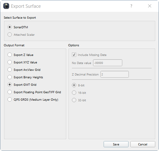
DMagic Export Dialog
Exported Surface can either be a SonarDTM or an Attached Scalar depending on what you choose from Select Surface to Export.
When saving the data, areas of the surface containing no data may be included with the output file if the Include Missing Data option is on. If missing data is included, a special value is written for these data points, indicated by the No Data Value text field.
When writing a binary file, you may specify either writing an 8-bit or 16-bit, or a 32-bit unsigned integer values representing the heights.
When exporting to ASCII X and XYZ Grids, there is an option to specify decimal precision of the Z value being written.
Calculate Slope
DMagic Calculate Slope Dialog
Surface slopes can be calculated using the Tools > Compute Slope menu option. The dialog box in the figure above allows the user to compute a surface that represents the maximum slope at each grid center of the currently loaded SD. The generated surface will have the same dimensions as the original surface file and represents the maximum slope from each cell to any of its neighboring cells.
For the generated surface, each cell represents the maximum slope to any of its neighbors written in decimal degrees. You can optionally specify the slope range bounds for the generated surface. This is useful if you want the range to correspond to a particular range of colors in a given color map.
The created scalar file can then be used in the shading process to drape the scalar color over the DTM. The values of the scalar can also be appended to the ".sd" when the Fledermaus objects are assembled. This means that when the surface of the object is picked in Fledermaus it will return X, Y, Z, and slope. Alternatively the user may create another surface where the Z value of the DTM is the slope.
If the resulting surface will be an attached Scalar to the current SD or a copy of the current SD, the SD can be re-shaded using the new attached scalar if Re-Shade with attached scalar is toggled one.
Calculate Rugosity
DMagic Calculate Rugosity Dialog
Rugosity is a measure of surface roughness and it can be created using the Calculate Rugosity command. The Gridding Window specifies the grid size surrounding a cell that will be used to calculate the rugosity value. By default the output surface will contain the full range of rugosity values, however a custom range can be specified to restrict the output to the user supplied values. There are three output options for the generated surface, with the default being to attach it to the original source SD file. There is also an option to create a copy of the source SD before attaching the rugosity, as well as an option to create a standalone SCALAR file.
If the resulting surface will be an attached Scalar to the current SD or a copy of the current SD, the SD can be re-shaded using the new attached scalar if Re-Shade with attached scalar is toggled one.
Interpolate
The surface interpolation tool allows for small holes in a surface or scalar to be filled in using values from one or more of the surrounding cells. The interface for setting up the interpolation is displayed in the figure below. Four options are available for determining the interpolated values:
Average: Calculates the average value of all surrounding cells
Minimum Value: Uses the maximum of all surrounding cells
Maximum Value: Uses the minimum of all surrounding cells
Fixed Value: Uses the value supplied by the user
DMagic Interpolate Dialog
Once the interpolation method has been chosen, the next step is to determine what cells will be filled in by the interpolator. This is done by setting the minimum number of neighbors required for a cell to be filled in, ranging from 1 to 8. You can also set the number of times the algorithm runs over the entire grid by setting the Number of Iterations pull down menu.
Resample
The resample operation can change the number of rows or columns in a surface. This is useful to change the resolution of an SD, for example to make it smaller in size. This operation does not affect the geo referencing bounds. By default, the ratio of rows to columns is not allowed to change, that is the aspect ratio is preserved. By un-checking the Constrain Ratio check box, the aspect ratio can be changed, as shown in the figures below.
DMagic Resample Dialogs
Instead of resampling based on the number of rows or columns, the surface can also be changed by specifying the X and Y cell sizes.
Surface Statistics
DMagic Surface Statistics Dialog
Surface statistics of the loaded surface can be viewed using the Tools > Surface Statistics menu option. The Surface Statistics dialog box, shown in the figure above, will appear. Properties of the current data set will be shown in the left text box, while the Surface Statistics Information text box is populated with statistics about the data set.
The Save As button allows to save the statistics to specified text file.
History Sub-Menu
DMagic contains tools to view and manage History items for a project. Each project contains a list of history items that each represents an operation that has been process as part of the current project and are sorted by the time.
View Information
View Information launches a dialog that displays the history information of the currently selected history item from the Project History List.
Close: Closes the History Information Dialog.
Save As: Saves the current information to a text file.
View Workflow: Some operations save all the parameters used to process the operation in a separate XML workflow file. This file can be used to rerun the operation again using the same input/output files or by using new input/output files. They can also be used to assist in Troubleshooting. When the View Workflow button is clicked, the XML workflow is displayed below the History Item information. To hide the Workflow, click the Hide Workflow button.
Next >: Displays the History Information for the next item in the project history list.
< Previous: Displays the History Information for the previous item in the project history list.
Remove History Entry
Removes the current selected History Item from the project.
Remove All Entries
Removes all History Items from the project.