
|
|
Introduction
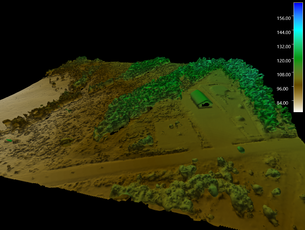
The Terrain Mesh object is similar to the solid model object but designed to represent models of a surface represented as a set of shaded triangles and is normally produced using one of the Fledermaus meshing methods. In addition to the terrain triangles a scalar of point density associated with each triangle is also stored which can help separate the real data from extraneous noise or artifacts from the meshing computation process. Terrain meshes can also have imagery texture mapped onto the surface for display.
Storage Format
Fledermaus Terrain Meshes are stored in files with the .mesh extension
Properties
In addition to the standard object properties and bounds, solid models have additional properties regarding the 3D model:
|
Property Name |
Description |
|---|---|
|
Indices Count |
The number of indices used to organize the vertices into faces. |
|
Meshes Count |
The number of distinct meshes used by the model. |
|
Vertices Count |
The total number of vertices in the model. |
Attributes
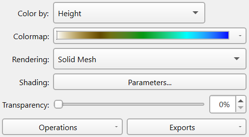
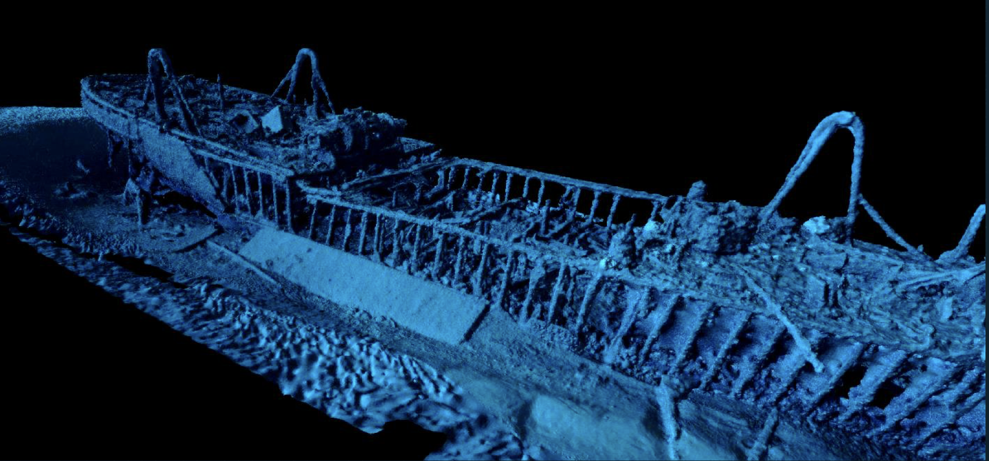
The Color by attribute can be one of Height, Single Color, Texture or Scalar. The height simply maps the height of the vertices through the given color map to determine the color of each triangle vertex. The single color gives each vertex the same color although the mesh is still illuminated based on a lighting model. The Texture option if present applies the texture onto the mesh and illuminates it as well. The scalar option maps the triangle face density through the color map to shade the surface based on how many source points contributed to each mesh face. This is very useful when combined with the Clip Mesh operation.
The Colormap allows the selection of the color map to use for rendering the object along with control over the mapping range.
The terrain mesh can either be rendered in the default shading as a solid mesh or a wire frame mesh.
The Shading Parameters button brings up the illumination control dialog as described here.
Operations
Change Object Coordinate System...
Allows you to manually set the coordinate system of the object. This should only be used if the object somehow ended up with the wrong coordinate system for its data. No re-projection is done, you are just telling it that this new coordinate system is what the object should have been in in the first place.
Clip Mesh
When a terrain mesh is produced with the Poisson reconstruction algorithm it generally creates some interpolated triangles especially near the edges of the model that don't actually have any points associated with them. The density scalar produced at the same time will have a zero count for these triangles and by default the mesh is clipped to [ 1.0, maxDensity ] which hides these triangles. The Clip Mesh operation allows one to control this mapping to clip out a portion of the density range. It uses the standard color map range mapping tool to do this. If you want to see the entire model without any clipping click the Reset button in the dialog. One can set the minimum clip bound by left clicking the mouse on the density histogram and set the maximum by right clicking on the histogram. If you know the values you want you can directly enter them into the User Range input fields.
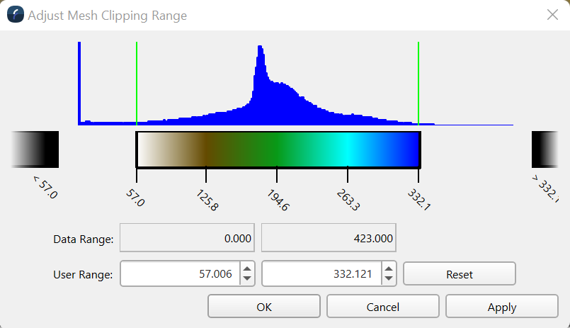
Clicking the Apply button with apply any changes you have made so you can see the results without having to close the clipping dialog. When you have the desired adjustment click the Ok button to apply and close the dialog.
Slice Mesh
The slicing tool dynamically applies the slicing operation to the terrain mesh as long as the Enable Slicing control is checked on.
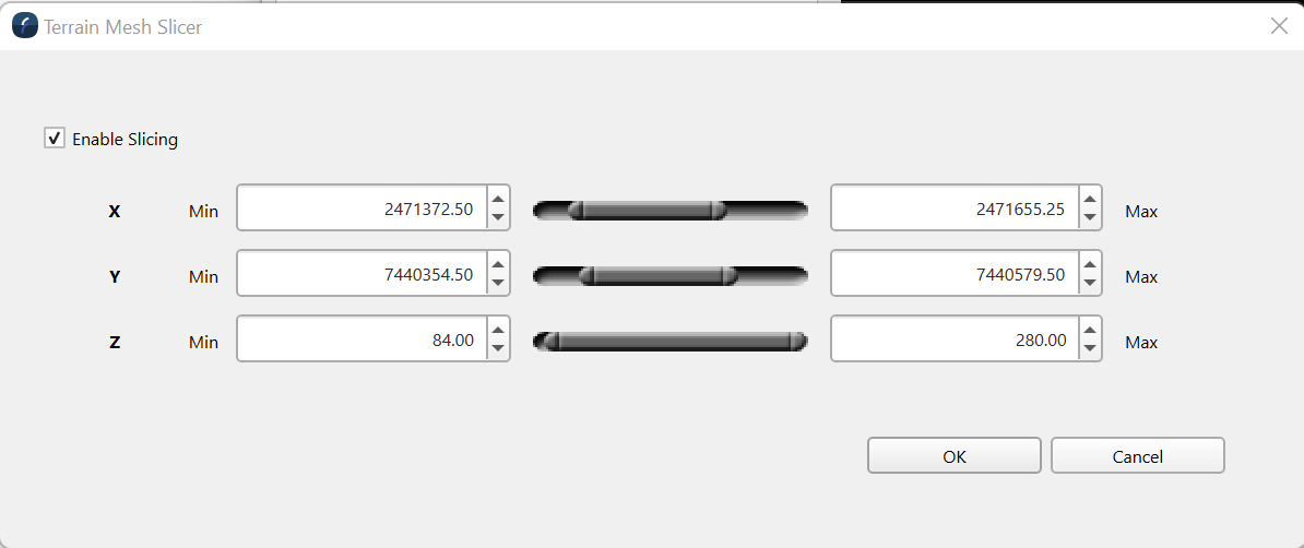
You can use the doubled ended slider to crop parts of the mesh based on the axis. Left click the left end of the slider and drag to adjust the minimum value and left click and drag the right end of the slider to adjust the maximum value. As you adjust the sliders the terrain mesh will dynamically show the effect of one's changes. Click Ok to set the slicing amounts.
Exports
Export to 3D Model File
The terrain mesh object can be written out in a variety of standard 3D modelling formats which makes it possible to bring terrain mesh objects into other 3D modelling packages such as Blender. The File > Import Terrain Mesh option lets one re-import the exported terrain mesh.
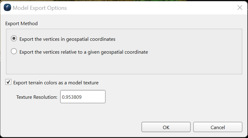
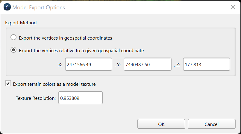
By default the Export the vertices in geospatial coordinates option exports the model as it says with its actual geo-spatial coordinates. However, if the goal is to import the model into Blender or some other modelling package then those packages generally cannot handle geo-spatial coordinates. Normally they want the model to be around (0.0, 0.0, 0.0 ) and in a basic metric such as meters. This can be done using the Export the vertices relative to a given geospatial coordinate option as shown below. By default the dialog will have the coordinate of the lower left corner of the model but one can enter any desired coordinate. When the vertices are exported this value is subtracted from the actual vertex geospatial coordinate. If one want to later re-import the model back into Fledermaus the offset can be re-applied as long as one remembers what offset coordinates where used in the export.
If the Export terrain colors as a model texture is off then no color values are assigned to the exported vertices. If one wants to see the terrain mesh in a package like Blender when this option will need to be one. In this instance during the export Fledermaus will create a colored texture based on the current visualization settings and save that will the model. By default the system will guess at the resolution to make the texture based on the average size of the triangles in the terrain mesh model although one can control it as desired. The maximum size of the texture that can be created is currently 8192 x 8192 pixels.
Return to Fledermaus Visual Objects
Return to Fledermaus Reference Manual