
Description
Driver to decode multibeam data from an Imagenex (http://www.imagenex.com/) Model 881L profiling/Imaging system. Driver can also be used to control the system from the user interface located in the Controller's Echosounder Settings dialog. The driver serves as a client when it sets up a TCP/IP connection to the sonar system. For every sounding the driver interrogates the 881L for data by sending it a switch command. The driver will receive and decode the beam data and transfer it into the Qinsy system.
Note that when using this driver the sonar can NOT be controlled by the Win881L application.
Decoding Notes
Driver decodes raw range and angles (no beam intensity) from the data. Driver uses the arrival time of the packet as the observation time, since the 881L sonar can not be synchronized to UTC time the arrival time may be subject to network latency. The reported angles are with respect to the reference direction of the sonar head. The ranges are reported in 2 millimeter or 10 millimeter units depending on the range. The ranges are always valid for a default sound velocity of 1500 m/s regardless any user settings.
The 881L system delivers a continuous stream of soundings which are buffered by the driver. The driver recognizes the end of a scan by monitoring the decoded rotating direction. If a swap over of direction is detected then the driver will decode the buffered soundings as a complete ping. If the 881L is scanning in continuous 360 degree mode then the scan direction will of course not change. In that case the zero crossover direction is used to detect an end of scan. Either way if a scan takes longer then 20 seconds to finish then it will be decoded in multiple parts to prevent too old multibeam data entering Qinsy with the risk that attitude data is no longer available.
Interfacing Notes
To minimize the chances of network latency and hence wrong decoded observation times we strongly advise to connect the Sonar directly to the Qinsy PC by a cross-over network cable and NOT via a hub or switch.
System Configuration
When the 881L is used for profiling the transducer head should be mounted in such a way the head angle reports zero when looking straight down. For imaging (sector scanning) the head angle should report zero when looking in the forward direction.
The Win 881L software can not be operated simultaneous when this driver is used.
Database Setup
Add new multibeam system to the template, select Driver "Imagenex 881L Profiler". The default IP number is fixed to 192.168.0.5, the port number of the Imagenex 881L is 4040.
For profiling mode, roll, pitch heading offsets should be around zero, in imaging mode the pitch offset should be around +90°.
To prevent any attitude issues make sure that update rates for motion sensors are not set higher then typically 10-20Hz. Qinsy will buffer a limited number of pitch/roll and gyro readings and since a scan may take up to 20 seconds to finish it can occur that the process that calculates the beam position runs out of attitude information if update rate are too high (>25 Hz).
The node defined for the transducer should be located in the acoustic center of the transducer head, refer to manufacturers' documentation for details on the acoustic center.
Online
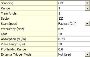
The operating settings of the sonar are modified through the Echosounder Settings dialog Control tab of the Controller.
The following settings can be modified:
|
Command |
Description |
|---|---|
|
Scanning |
On, Off or Hold, which pauses the 881L head rotation. |
|
Range |
Select from 1, 2, 3, 4, 5, 10, 20, 30, 40, 50, 60 ,80, 100, 150 and 200 Meters |
|
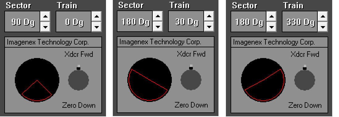
Train Angle |
Sets the direction for the midpoint of the currently defined sector in 3 deg. steps.
|
|
Sector |
Sets the width of the scan defined sector in 3 deg. steps.
|
|
Scan Speed |
Select from No Speed, Slow (0.3), Med. (0.6), Fast (0.9), faster (1.2), Fastest (2.4).
|
|
Frequency (kHz) |
The 881L is a multi-frequency system that can operate with customized configurations or revert to default settings to match appropriate operating range scales. Enter Min = 175, max = 1175 kHz. Standard default settings are: Range 1-5m = 310 kHz, Range 10-100m = 675 kHz, or Range 150-200m - 1 MHz.
|
|
Gain |
0 to 40dB in 1dB increments. Increase to get higher return levels, decrease to get lower return levels. |
|
Absorption |
0 to 255 = 0.00dB/m to 2.55dB/m.
Recommended values: 330kHz: 10 (0.1dB/m); 675kHz: 20 (0.2dB/m); 1MHz: 60 (0.6dB/m) Absorp tion and spreading loss are the main components of the Time Variable Gain (TVG) computation. Absorption is influenced primarily by frequency and the chemical compounds of boric acid and magnesium sulphate. It is highly recommended that the local absorption value be entered. In some circumstances, increasing the Absorption value will allow the system to rapidly increase gain to capture the reflected energy that has been dissipated by seafloor absorption or scattering in the water column. |
|
Pulse Length |
Length of acoustic transmit pulse in microseconds. 10 to 1000μsec in 10μsec increments.
|
|
Profile Min. Range |
Minimum range for profile point digitization. 0 to 25meters in 0.1 meter increments.
|
|
External Trigger Mode |
Select from Not Used, Positive Flank, or Negative Flank. The sonar head will transmit as soon as it detects the external trigger pulse. If a trigger pulse has not been found after a period of 2 seconds, the sonar will transmit as normal. |
Sector/Train Angle Note
These images illustrate the relationship between Sector and Train Angle:
Frequency Note
The default configuration for Win881L automatically adjusts the operating frequency, absorption and pulse length with range. The following Table describes this relationship:
|
Range
|
Frequency
|
Absorption
|
Pulse Length (μs) Polar Mode |
Pulse Length (μs) Sector/Sidescan Mode |
|---|---|---|---|---|
|
1 |
1000 |
0.6 |
20 |
10 |
|
2 |
1000 |
0.6 |
20 |
10 |
|
3 |
1000 |
0.6 |
20 |
10 |
|
4 |
1000 |
0.6 |
20 |
10 |
|
5 |
1000 |
0.6 |
60 |
30 |
|
10 |
675 |
0.2 |
60 |
30 |
|
20 |
675 |
0.2 |
100 |
50 |
|
30 |
675 |
0.2 |
160 |
80 |
|
40 |
675 |
0.2 |
220 |
110 |
|
50 |
675 |
0.2 |
260 |
130 |
|
60 |
675 |
0.2 |
320 |
160 |
|
80 |
675 |
0.2 |
420 |
210 |
|
100 |
675 |
0.2 |
540 |
270 |
|
150 |
310 |
0.1 |
800 |
400 |
|
200 |
310 |
0.1 |
1000 |
530 |
The frequencies in the above table are designed for use with the Fan Beam Imaging Sonar (Model 881-000-500/501) only!
The Pencil Beam Profiling Sonar (Model 881-000-520/521) has a frequency limit of 600 kHz to 1 MHz.
Scanning Speed Note
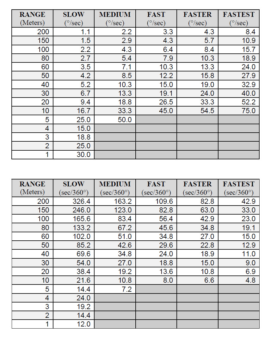
For more information on these settings please refer to the Imagenex documentation.
Note that every time Qinsy is started the Scanning is turned off to prevent any damage to the transducer caused by pinging in the air. Settings will be stored in the registry when the Controller is closed.
Command Line Parameters
|
"YELLOW" |
Start driver in Yellowfin Sidescan mode |
|
"881L" |
Start driver in 881L profiler mode |
Additional Information
For more information refer to Imagenex website: http://www.imagenex.com/